


Content last revised on September 19, 2026
2RI100E-080 Thermal-Electrical Optimization: Thermal Interface Material Spreading Across Practical Tuning
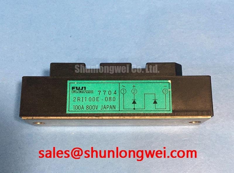
With the equipment isolated and discharged, first compare the cold diode-mode readings between each accessible power terminal pair and the original circuit drawing before installing the 2RI100E-080. This Fuji Electric unit is identified as a Power Diode Module, rated at 2500 V and 100 A as Official Datasheet Specifications. A diode-mode test can help reveal an unexpected short circuit or an open current path, but readings must be compared against the verified module connection diagram because terminal functions are not established by the rating label alone.
| Parameter | Value | Classification |
|---|---|---|
| Manufacturer | Fuji Electric | Product identification |
| Device type | Power Diode Module | Official Specification |
| Rated voltage | 2500 V | Official Specification |
| Rated current | 100 A | Official Specification |
Inspect the baseplate contact surface, heatsink flatness, mounting-hole condition, and power-terminal hardware before applying thermal interface material. The 2500 V, 100 A nameplate rating defines the electrical identity of this diode module; it does not establish permissible heatsink temperature, junction-to-case thermal resistance, surge current, fuse clearing energy, or mounting torque. Those values must be taken from the original Fuji Electric documentation for the exact module revision.
A thin, continuous thermal compound layer is a Design Consideration: its purpose is to fill microscopic interface variation while avoiding localized excess that can interfere with stable seating. Tighten mounting points progressively in a balanced sequence so contact pressure develops evenly across the baseplate. Do not infer an approved torque from the terminal size or housing appearance. The system integrator should use the documented mechanical instruction or the equipment manufacturer’s service specification.
⚡ Bench Tip: Keep the module, meter probes, and test leads protected from electrostatic discharge, then record cold-state readings before and after mounting so an installation-related change is not mistaken for an incoming electrical defect.
For assemblies under thermal cycling, compare heatsink contact marks after removal only when the equipment procedure permits it. Uneven transfer compound distribution can indicate a mounting or surface-condition issue, but it does not independently prove junction damage. Fuji Electric’s power semiconductor information provides useful manufacturer context when confirming the appropriate document family.
Transient Dynamics & Electrical Design: AC-to-DC Bridge Behavior Around Controlled Firing Systems
The 2RI100E-080 is a diode module, so it has no gate terminal and no firing-delay angle to adjust. Any firing-angle control from zero through 150 degrees belongs to external thyristor valves or other controlled switching devices in the surrounding system, not to this diode module. Treating a diode module as a triggered device can lead to an incorrect test plan and an incorrect replacement assessment.
When evaluating a grid-tied static var compensator or thyristor-switched capacitor cabinet, engineers should trace the actual AC source, controlled switching stage, rectifier stage, DC bus, and protective components. The diodes in a rectifier stage conduct according to applied polarity and circuit impedance; reactive-power behavior and power factor are determined at system level by the controlled branches, capacitor banks, reactors, load conditions, and control sequence.
A diode module such as the 2RI100E-080 can therefore be assessed for its documented voltage and current class while the external control topology is validated separately. Where an adjacent diode module is being compared during service planning, the 2DI100A-120 should be checked against its own documentation, connection arrangement, thermal interface requirements, and application limits rather than treated as an automatic substitute.
Benchtop Waveform Tuning: Semiconductor Protection Fuse Selection for 2RI100E-080
Fuse selection requires the module’s applicable surge and overload limits plus the fuse manufacturer’s pre-arcing and total clearing I²t data. No I²t withstand figure, fuse coordination table, or fault-clearing energy limit is provided in the stated official parameters for this product, so a numerical fuse recommendation would not be supportable here.
As a Design Consideration, review the complete fault path: source impedance, transformer contribution, busbar layout, capacitor discharge energy, downstream short-circuit location, and the interruption behavior of the selected semiconductor fuse. The protection study should verify that prospective fault energy is coordinated with the documented device capability and with upstream protection. A fuse can limit fault energy, but it cannot be assumed to prevent every mechanical or electrical consequence of a severe system fault.
During bench investigation, isolate the diode module from parallel paths where the service procedure allows, then check each expected diode conduction direction with the same instrument range and lead polarity. A reading that differs from the remaining paths may indicate a condition requiring further isolation and circuit-level verification; it is not enough to assign one cause without checking connected snubbers, bus capacitors, and external semiconductors.
For a documented comparison path, the 2DI100Z-140 is a separate product reference. Voltage class, current rating, package configuration, terminal mapping, and manufacturer limits must all be confirmed before any compatibility decision.
Benchtop Waveform Tuning: Thermal Avalanche Margins During High Peak Conditions
A 10 ms half-cycle surge assessment requires the official sinusoidal surge-current rating, starting junction condition, repetition conditions, and reverse-voltage recovery requirements. These values are not included in the available official parameter set for the 2RI100E-080. It would be inaccurate to assign an ITSM value, thermal-avalanche margin, or allowable reverse-voltage reapplication condition from the 2500 V and 100 A ratings alone.
Engineering Recommendation: capture voltage across the diode module and current through the relevant branch during controlled commissioning, using appropriately rated isolated measurement equipment. Review waveform symmetry, repetitive peak behavior, heatsink condition, and the time relationship between line recovery and diode current decay. The system engineer should verify peak voltage margins against the DC-link and line conditions during switching tests.
Preventive troubleshooting should also include inspection of terminal contact surfaces, conductor strain relief, enclosure contamination, and the measured condition of associated capacitors and protection parts. For broader context on how power-conversion architectures and component technologies are evolving, see Future of Power Electronics. Additional regional manufacturer context is available through Fuji Electric Europe Semiconductor & Power Electronics.


