

Content last revised on November 12, 2026
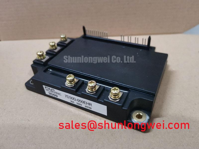
7D30D-050EHR Identification and Pre-Commissioning Checks
- Isolate the equipment, verify DC-link discharge, and disconnect the gate driver before checking terminal impedance.
- Match the module marking and terminal arrangement to the equipment schematic before removing existing connections.
- Inspect the heatsink contact surface, cooling passages, and terminal hardware for contamination, distortion, or heat discoloration.
- Check for moisture and condensation around the gate connections before applying control power.
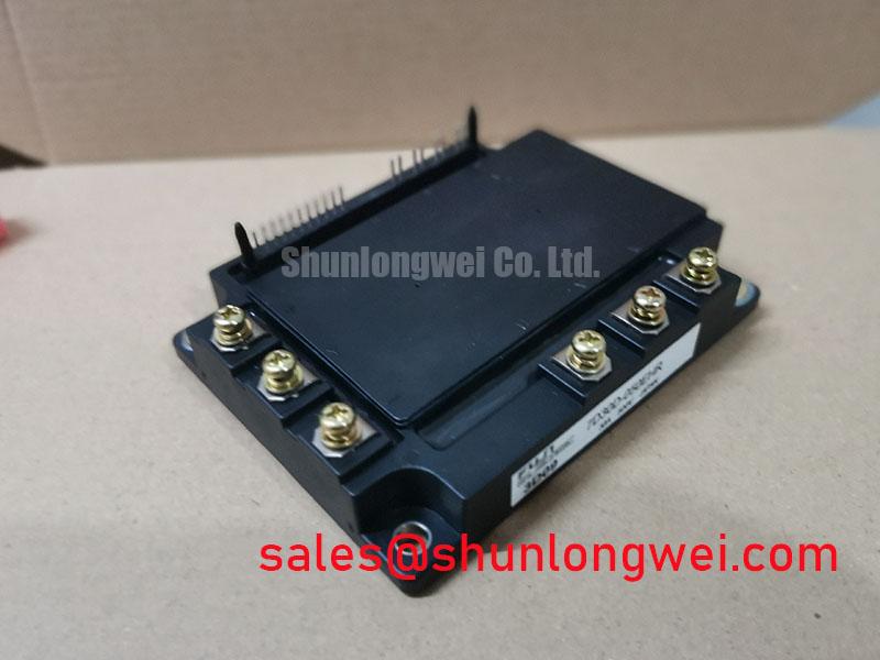
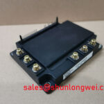
The 7D30D-050EHR is a Fuji Electric IGBT Module with the electrical ratings and package designation below. These specifications establish its identification baseline; commissioning also requires the equipment’s connection drawing and protection settings. Electrical ratings must be checked against the manufacturer’s datasheet conditions and are not recommended operating points.
| Specification | Product value |
|---|---|
| Manufacturer | Fuji Electric |
| Part Number | 7D30D-050EHR |
| Collector-Emitter Voltage (Vces) | 600.0 V |
| Rated Collector Current (Ic) | 300.0 A; subject to the datasheet’s specified conditions. |
| Package | Fuji Power Module |
| Configuration / Topology | IGBT Power Stage |
| Integration details | Consult Datasheet for terminal mapping, gate limits, thermal characteristics, mounting requirements, and short-circuit withstand conditions. |
Field Diagnostics & Commissioning: PCB Gate Loop Layout Symmetry in 7D30D-050EHR Topologies
Trace the gate-driver return to its emitter connection before judging an oscillating gate waveform. Design Consideration: shared impedance between the switching-current path and driver return can introduce feedback into the gate loop. Where the documented terminal arrangement provides an auxiliary emitter connection, keep that return separate from the main emitter-current routing; do not assume this package includes a Kelvin terminal.
Compare outgoing and returning gate paths for unnecessary loop area, unequal routing, and proximity to switching conductors. Maintain separation appropriate to the equipment’s working voltage, insulation system, and contamination conditions rather than imposing an arbitrary board clearance. During controlled commissioning, measure gate-emitter voltage at the device connections with suitable differential instrumentation; a measurement referenced elsewhere can include return-path disturbance.
For replacement assessment in a heavy-duty variable-frequency AC motor drive, compare terminal functions, mounting geometry, driver compatibility, and cooling interfaces. The 2MBI300L-060 can be included in that comparison, but a shared rating class does not establish interchangeability.
Benchtop Waveform Tuning: Mitigating Stress via Dynamic Braking Chopper Operation on 7D30D-050EHR
Record DC-link voltage during controlled deceleration to determine whether regenerative energy is being managed by the existing braking circuit. Design Consideration: a braking chopper diverts energy from the DC link into a resistor; its semiconductor arrangement must come from the equipment schematic, not an assumption that the 7D30D-050EHR contains an internal braking switch.
Evaluate the braking transistor and resistor against deceleration energy, repetition rate, pulse loading, and cooling recovery. Observe switching overshoot and resistor temperature during staged testing. Resistor continuity alone does not demonstrate adequate braking performance, and an overvoltage event can also involve control timing, wiring, or operating conditions.
If the equipment parallels switching modules, compare branch currents and thermal conditions with symmetrical busbar routing. A positive temperature coefficient of collector-emitter saturation voltage can assist static sharing only within the applicable device characteristic region; it is not a universal sharing guarantee. Dynamic sharing also depends on gate paths and commutation inductance. The IGBT Loss Analysis Technical Reference explains the conduction-loss and switching-loss trade-off relevant to this assessment.
Assembly Integrity & Layout Architecture: Assessing Gate-Emitter Integrity in 7D30D-050EHR
Use diode-check mode on an isolated module to compare conduction paths against the documented internal circuit, including antiparallel diodes where shown. Engineering Recommendation: record polarity and test conditions rather than applying a universal forward-voltage threshold. Connected snubbers, driver components, and residual gate charge can alter readings.
A handheld meter can reveal gross shorts or unusual leakage indications, but it cannot establish gate-dielectric integrity under operating stress. Compare suspect readings with the documented circuit and a known-good assembly under equivalent conditions. Do not apply an insulation tester across gate-emitter terminals unless an approved device-specific procedure permits it.
Inspect the baseplate mating surface and thermal interface for separation, contamination, or uneven contact. Reassembly should follow the specified interface-material application and tightening sequence using calibrated tools. Set inspection intervals from equipment duty, thermal trends, and environmental exposure, including condensation after temperature changes.
Maintenance Note: Trend terminal and heatsink temperatures under comparable load, and check airflow before attributing a temperature increase to the module.
7D30D-050EHR Operational Boundaries: Mitigating Hard-Switching Transients
Evaluate fault detection together with shutdown behavior, because interrupting excessive current can generate inductive overvoltage. Design Consideration: type-I faults involve turn-on into an existing short circuit, while type-II faults develop during conduction; both require coordinated sensing, driver response, and controlled turn-off.
A detection target below ten microseconds is not an established 7D30D-050EHR withstand rating. Protection timing must remain inside the applicable short-circuit safe operating area under its stated voltage, gate-drive, and temperature conditions. Two-stage soft turn-off can reduce abrupt current interruption, but its timing and gate control require system validation.
The Fuji Electric V-Series IGBT Application Manual provides general application guidance, not model-specific qualification for this part. During protection validation, capture collector-emitter overshoot, gate disturbance, and fault-clearance behavior together. Review snubber placement and commutation-loop routing against those measurements before releasing the repaired assembly.