
Content last revised on September 16, 2026
Preventing Spurious Faults: High-Current DC Rectifier Topologies for 6RI75P-160-51
Before fitting the 6RI75P-160-51, isolate the rectifier assembly, inspect the mating busbars and terminals for heat discoloration or looseness, and verify that the measured and documented operating conditions remain within the module’s 1600 V repetitive peak reverse-voltage rating and 75 A average forward-current rating under the applicable datasheet conditions.
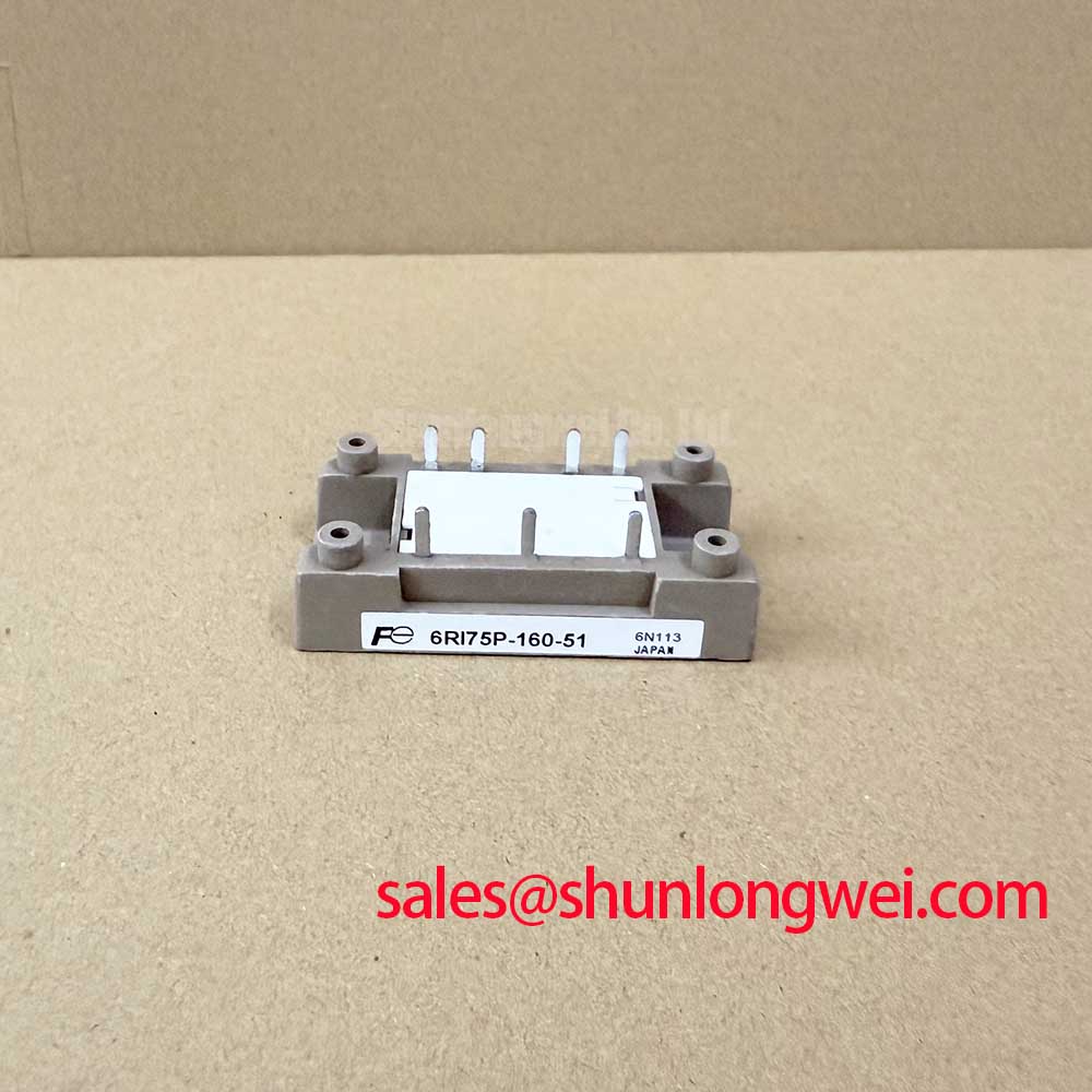
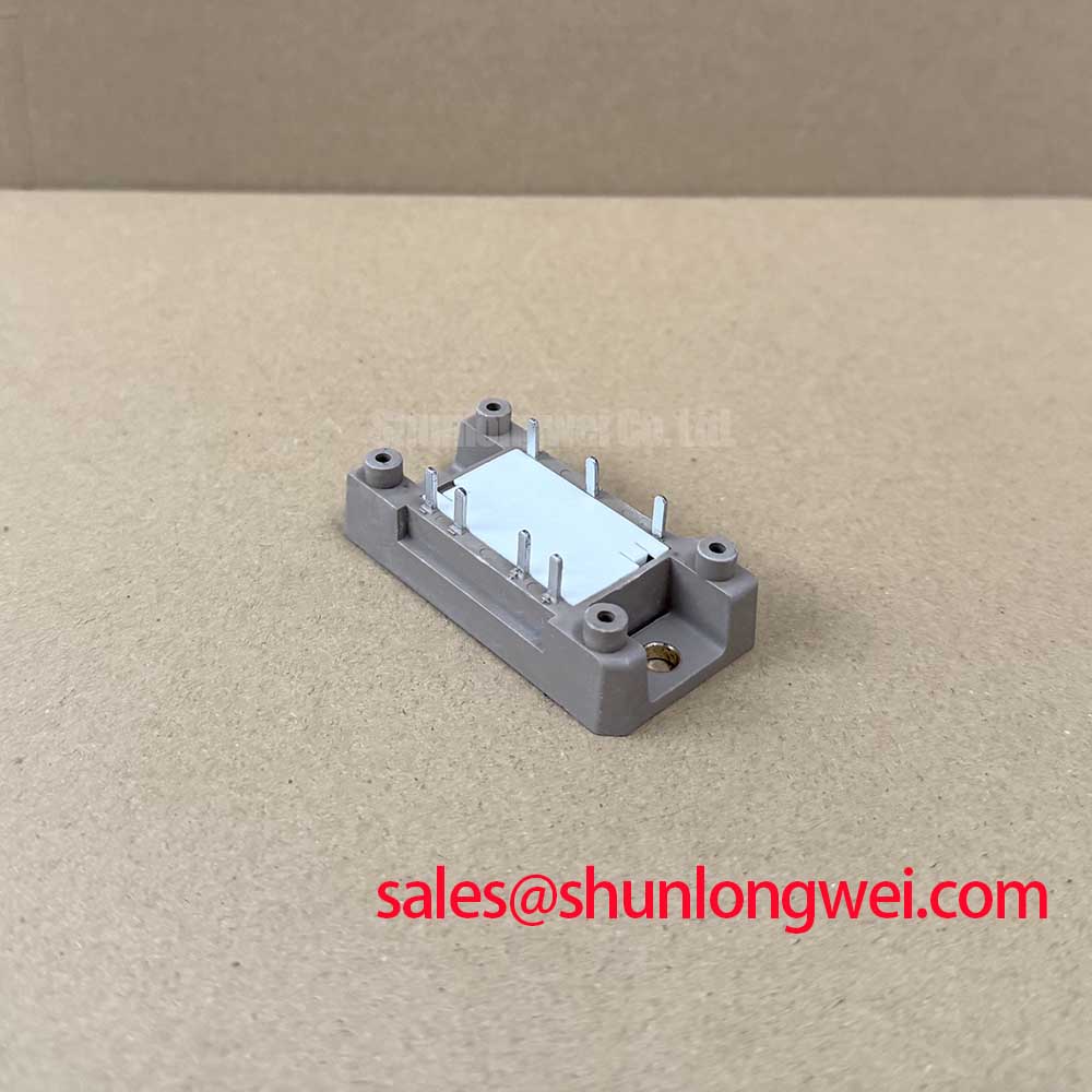
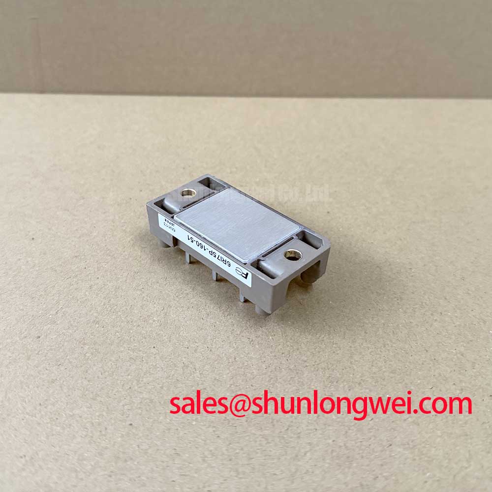
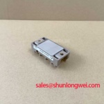
The Fuji Electric 6RI75P-160-51 diode module is specified for Vrrm 1600 V, Io 75 A, Ifsm 1000 A at 60 Hz, a junction-temperature range of minus 40 to plus 150 degrees C, and 2500 V AC isolation voltage. These are official datasheet specifications and should be checked against the original rectifier documentation before any repair release.
In a six-pulse bridge, current continuity and commutation behavior depend on the transformer, DC-link impedance, cabling, and load. A twelve-pulse arrangement adds phase-shifted bridges and requires deliberate current-sharing checks through the interphase transformer. For a high-current green hydrogen electrolyzer DC power rectifier, the module current rating must be evaluated as part of the complete bridge current path, rather than treated as a direct indication of total plant DC output.
Fuse coordination is a Design Consideration. Compare the fuse manufacturer’s pre-arcing and clearing I2t curves with the prospective fault energy and the system’s allowable semiconductor surge capability. The published 1000 A surge forward-current value at 60 Hz is useful for assessing short-duration non-repetitive surge exposure, but it is not a substitute for a coordinated protection review. Record busbar contact condition, terminal hardware condition, and the approved tightening procedure from the equipment manufacturer during each planned shutdown.
Maintenance Note: Monitor terminal contact temperature rise and verify that the cooling air path remains clear whenever the rectifier cabinet is serviced.
Where the original equipment bill of materials permits a comparison, engineers can review the 6RI75G-160B against the installed module’s electrical, mechanical, and connection requirements; interchangeability must be confirmed from the equipment documentation.
Benchtop Waveform Tuning: Mitigating Stress via Reverse Recovery Charge on 6RI75P-160-51
Reverse-recovery behavior should be assessed on an isolated test arrangement that reproduces the installed commutation path as closely as practical. The supplied official ratings establish the voltage, average-current, surge-current, temperature, and isolation boundaries, but they do not provide an official value here for reverse-recovery peak current or recovery time. Those values must be taken from the applicable manufacturer documentation and verified under the actual system conditions.
During waveform investigation, measure the commutation current, reverse-voltage excursion, and ringing at the device connection points with suitable differential measurement equipment. A pronounced recovery-current peak or persistent oscillation may indicate interaction among transformer leakage inductance, busbar geometry, DC-link capacitor placement, and the measurement setup itself. Compare results with a known-good phase path before assigning a cause.
Film capacitors are commonly evaluated as part of DC-link ripple-current control and transient containment. The operating principle and construction context are described in Film Capacitors in High Ripple Current DC-Link Applications. Their selection remains a system-level Design Consideration, requiring validation of voltage stress, ripple current, physical placement, and thermal conditions.
For electrolyzer rectifiers, do not infer diode switching performance from cabinet-level electromagnetic behavior alone. Cable routing, transformer shielding, control wiring, and enclosure bonding can each influence the observed waveform. The system engineer should verify peak margins against DC-link voltage during switching and commutation tests.
Transient Dynamics and Electrical Design: Baseplate Thermal Resistance on 6RI75P-160-51
Thermal work begins with a clean, flat heatsink interface and an inspection of the module mounting surface before applying thermal interface material. The official minus 40 to plus 150 degrees C junction-temperature range defines the permitted junction-temperature boundary, not a predicted operating temperature or service life. Actual junction temperature depends on diode losses, heatsink performance, airflow, ambient conditions, current waveform, and the quality of the assembled thermal interface.
Baseplate thermal resistance must be obtained from the applicable manufacturer documentation where required for a thermal calculation. Do not assign a thermal-resistance value from a similar module. A Design Consideration is to spread the approved thermal compound uniformly, use the equipment manufacturer’s fastening sequence and torque specification, and inspect for uneven contact patterns after removal. Excess material, debris, or uneven clamping can impair heat transfer or introduce mechanical stress.
High-temperature engineering plastics are often considered in power-module packaging discussions because of their heat resistance and chemical stability. Material background is available at Polyphenylene Sulfide High-Temperature Engineering Plastic for Modules; it does not establish the internal construction of this specific module.
In preventive maintenance, check fans, filters, heatsink fins, cabinet seals, and condensation control as a complete thermal path. When recurring thermal alarms are present, compare phase-to-phase electrical loading and contact temperatures before deciding whether the issue is localized to the diode module, cooling system, or upstream transformer and buswork.
6RI75P-160-51 Thermal-Electrical Optimization: Dynamic Voltage Sharing and RC Damping in Practical Tuning
RC damping and series saturable-reactor decisions belong to the complete rectifier topology. Their purpose can include reducing commutation ringing, limiting transient voltage stress, and avoiding conditions that could produce unintended current redistribution. Component values cannot be responsibly prescribed from the 6RI75P-160-51 ratings alone; they must be established from measured waveforms, transformer characteristics, DC-link arrangement, and thermal testing of the installed system.
For parallel paths or multi-bridge arrangements, dynamic voltage and current sharing should be verified while the system moves through its expected load range. Inspect symmetry in busbar routing, connection resistance, cooling exposure, and transformer phase relationships. A measurement difference may indicate an assembly or system interaction and should be investigated against the known-good path instead of being attributed to one component without evidence.
Control-board isolation also deserves review when transient events coincide with alarms. Optical isolators and digital isolators need to be evaluated against the system’s measured common-mode conditions, grounding arrangement, and gate-drive or protection architecture. For broader discussion of high-voltage three-phase conversion considerations, see The 1200 V CoolSiC™ MOSFET Advantage in Three.
Where regenerative braking choppers or battery charge-discharge equipment share a DC bus with the rectifier, verify energy-routing behavior at the system level. Braking-resistor duty, converter control timing, capacitor condition, and rectifier commutation can affect the electrical environment seen by each module. Maintain records of waveform captures, thermal observations, and terminal inspections so later service decisions are based on comparable operating evidence.