



Content last revised on September 28, 2026
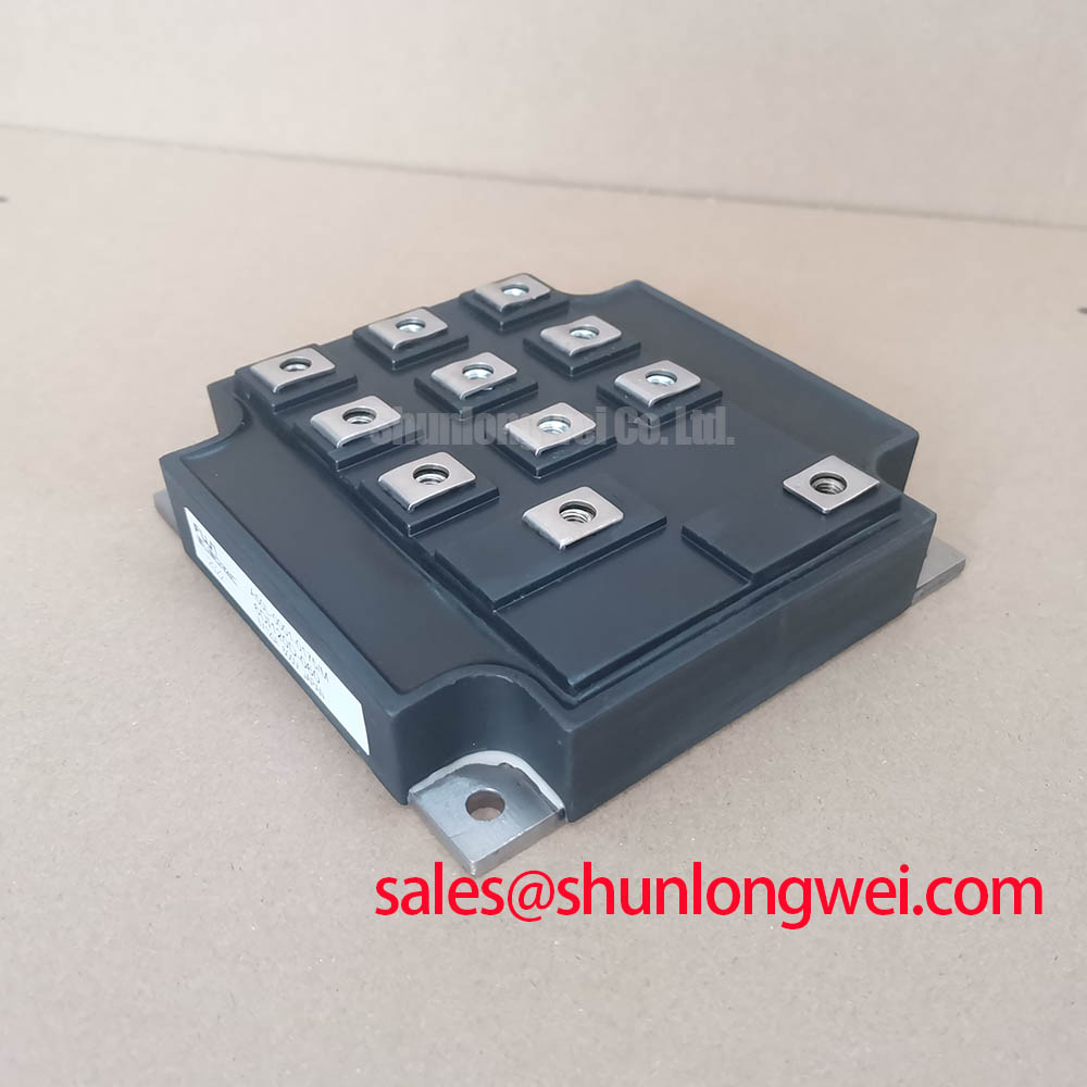
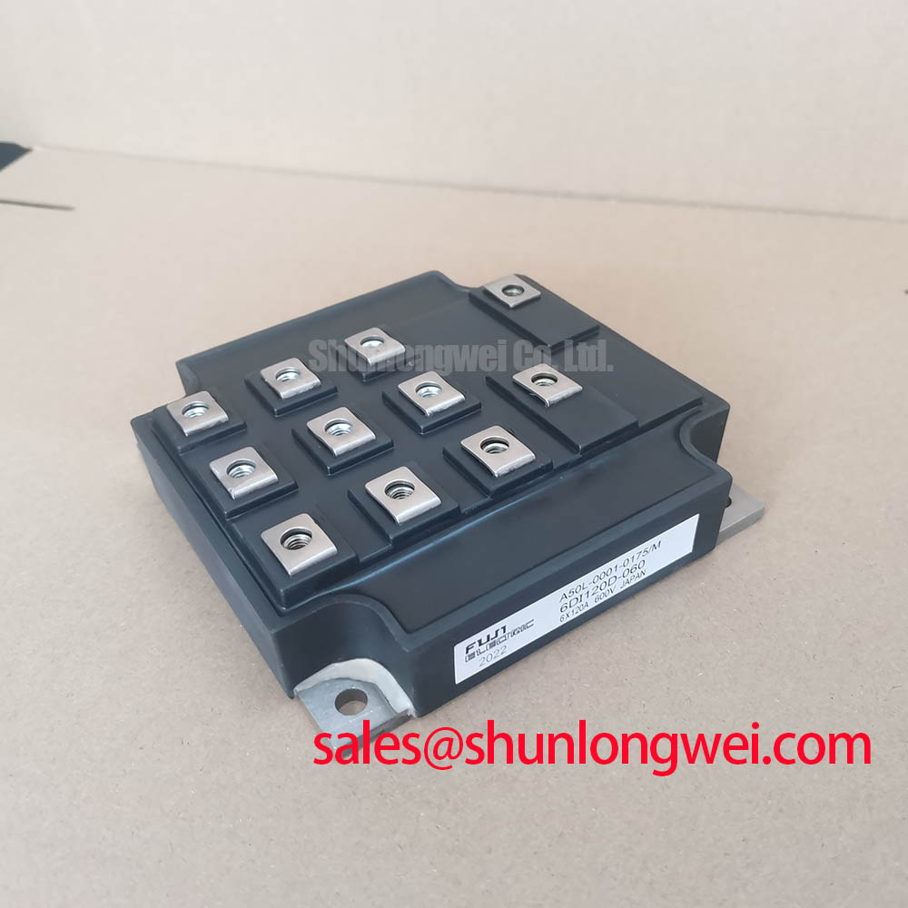
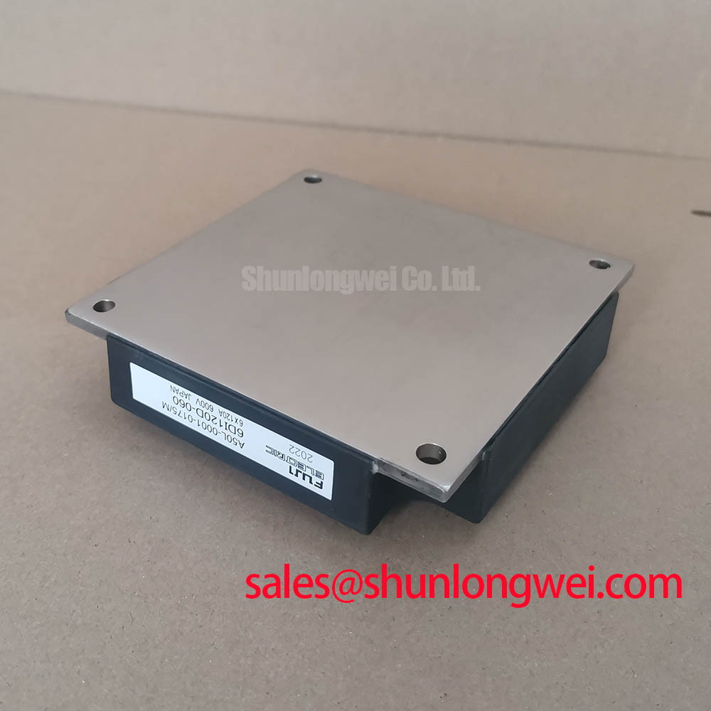
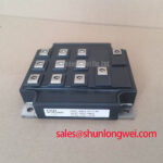
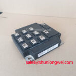
6DI120D-060 Fuji Electric 600V 120A Power Transistor Module
With the module fully isolated from the circuit, first verify the marking, inspect the power terminals and baseplate for mechanical damage, then record cold resistance and diode mode readings against a known good reference. The 6DI120D-060 is a Fuji Electric power transistor module specified at 600.0 V and 120.0 A, with a Power Transistor Module package classification. Gate, auxiliary terminal, switching, thermal, and isolation values should be confirmed from the applicable Fuji Electric documentation before replacement.
For incoming inspection, use an ESD-controlled bench and keep the module disconnected from the driver, DC link, and motor circuit. A diode mode check can help compare the observed semiconductor junction behavior between corresponding terminals, but the measured forward voltage should not be treated as a universal pass or fail threshold without the manufacturer’s test conditions. If readings change while the leads are repositioned, inspect the test fixture, residual charge, and connected snubber components before judging the module.
💡 Bench Tip: Discharge the surrounding DC-link circuit and compare all cold-state readings with a documented good unit before applying any gate signal.
6DI120D-060 Circuit Protection and Reliability in Busbar Layouts
In a forklift traction inverter or a related low-voltage material-handling drive, the replacement decision begins with electrical boundary verification: the system DC-link voltage and transient behavior must remain within the module’s documented ratings. The familiar relationship between switching overshoot, commutation current change, and stray inductance explains why a compact, symmetrical laminated busbar is often evaluated as a design consideration. The peak voltage rises with both parasitic inductance and current slew rate, so the system designer should minimize the commutation loop and verify the measured peak against the DC-link voltage during switching tests.
Do not assign a fixed busbar inductance, snubber capacitance, or clearance value to this module without the complete circuit, insulation system, operating altitude, and applicable safety requirements. Snubber selection should be based on measured ringing, capacitor pulse capability, voltage margin, and switching loss. Check the collector and emitter power paths for equal current distribution, clean contact surfaces, and low-inductance return routing. The Fuji Electric Power Semiconductor and IPM Modules resource provides manufacturer-level context, while the The Ultimate IGBT Knowledge Base can support broader topology and switching analysis.
6DI120D-060 Operational Boundaries for Baseplate and Thermal Installation
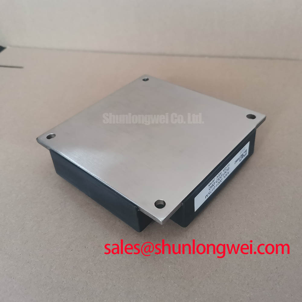
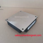
Thermal integration should be treated as a system-controlled process rather than a guaranteed property of the part number. Confirm the heatsink flatness, mounting-hole alignment, interface material compatibility, and required fastening sequence from the mechanical drawing and the equipment service documentation. A uniform thermal interface layer is a design consideration; excessive material, trapped air, contamination, or uneven screw loading can increase thermal resistance and mechanically stress the baseplate. The heatsink should be cleaned and inspected before installation, with the final interface verified after fastening.
Do not infer a permitted screw torque, baseplate convexity, isolation withstand value, or operating temperature from the 600 V and 120 A ratings alone. Those figures identify the electrical class and current rating, not the complete thermal operating envelope. If a high-side driver uses bootstrap power, the capacitor and recharge path should be selected from the actual gate-charge requirement, driver quiescent current, switching frequency, duty cycle, leakage, and required hold-up time. The system integrator should validate the driver supply under the real switching waveform. A nearby device such as 6MBI15L-060 may appear in a related inverter topology, but circuit compatibility must be checked rather than assumed.
6DI120D-060 Gate Loop Impedance and Cross-Conduction Control
Before connecting the replacement module to a controller, trace the complete gate-drive loop and identify whether the original assembly uses separate power and control returns. Terminal names and auxiliary connections must be verified from the original Fuji Electric drawing; they should not be reconstructed from package appearance alone. Short, tightly coupled gate and return paths generally reduce unwanted voltage developed across parasitic inductance. This is a design consideration that requires oscilloscope validation at the module terminals, not only at the driver output.
High dv/dt can couple through the device’s Miller-related capacitance and disturb the off-state gate voltage. Designers may evaluate a dedicated low-impedance active Miller clamp, interlock timing, and a negative gate bias only when these functions are supported by the selected driver and confirmed against the module’s gate limits. Investigate suspected cross-conduction by comparing both gate-emitter waveforms, the command timing, and the phase-leg current under controlled test conditions. Gate-loop ringing can also originate from probe grounding, shared return impedance, or an unsuitable driver layout.
Benchtop Waveform Tuning and Desaturation Protection
Desaturation protection should be coordinated with the driver, current path, blanking behavior, and fault response. A short-circuit protection interval must be chosen from the complete switching test, because the module’s public 600 V and 120 A ratings do not by themselves establish a short-circuit withstand time or SCSOA limit. If the driver supports two-stage soft turn-off, the first response can reduce gate drive in a controlled manner before the final turn-off action, while the power loop is monitored for inductive overvoltage.
During bench commissioning, begin with a current-limited DC source and confirm gate command polarity, fault-reset behavior, and driver supply stability. Use a properly rated differential voltage probe and a low-inductance current measurement method. If a desaturation event appears unexpectedly, inspect the collector-emitter voltage path, diode recovery interaction, blanking network, probe placement, and driver reference connection instead of assigning a single cause. The Stefan–Boltzmann discussion of radiative heat exchange in power enclosures at Stefan–Boltzmann Law for Radiative Heat Exchange is relevant when enclosure thermal behavior is being reviewed, but it does not replace direct junction-temperature and heatsink verification. For a neutral replacement comparison, engineers may evaluate QM200HA-HK against the original electrical, mechanical, gate-drive, and protection requirements.