

Content last revised on September 21, 2026
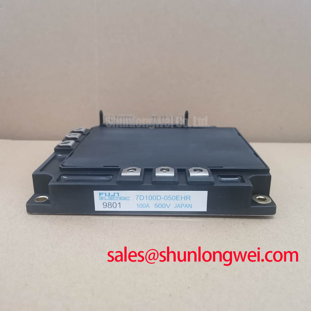
7D100D-050EHR Overview and Installation Checks
Before fitting the 7D100D-050EHR, isolate the drive, discharge the DC link according to the equipment procedure, and compare the existing module’s terminal arrangement, control connector orientation, and nameplate ratings with the original drive documentation.
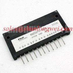
The Fuji Electric 7D100D-050EHR is a 7 in 1 Power Integrated Module specified for a 450 V collector-emitter voltage rating and a 100 A collector-current rating under the specified datasheet conditions. Its integrated power circuit combines a three-phase inverter bridge, rectifier function, and braking function for compact variable-frequency-drive power stages. The official maximum dissipation rating is 350 W per transistor. Official integrated protection functions include overcurrent and overtemperature protection.
| Official Specification | Value | Integration Relevance |
|---|---|---|
| Collector-Emitter Voltage | 450 V | Official datasheet voltage rating for DC-link and transient-margin evaluation |
| Collector Current | 100 A under the specified datasheet conditions | Official datasheet specification for inverter-load assessment |
| Maximum Power Dissipation | 350 W per transistor | Official datasheet specification for thermal-system assessment |
| Power Configuration | 7 in 1 | Three-phase bridge, rectifier, and brake-function integration |
| Integrated Protection | Overcurrent and overtemperature | Official integrated protection functions |
7D100D-050EHR Circuit Protection and Reliability: Heatsink Contact Pressure and Thermal Interface Control
Thermal contact begins with the mounting plane, not with the heatsink fan. Inspect the heatsink for corrosion, raised burrs, embedded debris, and local damage around mounting locations. A clean, flat contact surface helps the baseplate transfer heat consistently into the heatsink. Where a thermal interface material is used, its thickness should be controlled within the material supplier’s specified assembly range. A 50 to 100 μm bond line is a general industry assembly reference for thin thermal grease applications, not an official mounting specification for this Fuji Electric module.
Design Consideration: apply thermal interface material evenly and avoid trapped air pockets. Excess material can increase thermal resistance, while insufficient coverage can leave dry contact regions. Baseplate curvature, heatsink flatness, and clamping sequence interact during assembly, so technicians should tighten mounting screws progressively in an alternating pattern rather than fully tightening one location first. The final torque must be verified from the module mechanical documentation and the equipment manufacturer’s service procedure.
💡 Pro Tip: Tighten the module mounting hardware in a balanced sequence so contact pressure develops evenly across the baseplate before the final torque verification.
For a drive that reports overtemperature or suffers repeated thermal trips, do not assume that the power module alone is responsible. Check fan operation, airflow direction, blocked fin channels, thermal interface coverage, heatsink contamination, current loading, switching behavior, and temperature sensing paths. The 350 W per transistor rating is an official device limit, while the actual allowable operating loss is determined by the complete thermal path and the equipment operating conditions.
During repair assessment, confirm that the drive enclosure maintains intended clearances around DC bus conductors and control wiring. Separation helps reduce the chance that high-energy switching paths interfere with protection and feedback circuits. This is an Engineering Recommendation for the surrounding converter layout, not a claimed mechanical feature of the 7D100D-050EHR.
7D100D-050EHR Thermal Electrical Optimization: Dynamic Gate Impedance Control for Practical Tuning
The inverter section of the 7D100D-050EHR must be evaluated as part of the complete gate driver, DC link, busbar, motor cable, and protection system. High switching voltage slew rate can couple through parasitic capacitances and disturb a nonconducting switch command. This can contribute to unintended turn-on behavior or cross-conduction if the gate-driver return path, gate impedance, and timing are not validated under real switching conditions.
Design Consideration: dedicated low-impedance turn-off paths, active Miller-clamp functions, and negative gate bias are common gate-driver measures used in industrial IGBT converter systems. Their suitability, gate-bias values, and timing must be determined by the drive’s original gate-driver requirements and confirmed with switching measurements. These are system-level measures and are not presented as official gate-drive settings for the 7D100D-050EHR.
Dead time also requires practical verification. It must prevent simultaneous conduction in a bridge leg while remaining compatible with the motor-control strategy, switching speed, temperature range, and protection response. An oscilloscope measurement referenced to the intended gate-emitter path can reveal ringing, delayed turn-off, or a gate waveform that differs from the known-good channel. Test-equipment grounding and probe placement matter because a long probe ground lead can create misleading ringing.
Where a system uses parallel power paths, current balance should not be assumed from identical current ratings. IGBT conduction behavior changes with temperature, and the positive temperature coefficient of VCE(sat) can assist static sharing under appropriate conditions. Even so, symmetrical busbar geometry, comparable thermal paths, equal gate-drive conditions, and matched protection sensing remain essential Design Considerations. The system engineer should verify current sharing under representative load and switching conditions.
7D100D-050EHR integration should also consider motor-cable behavior. Long motor cables can create reflected-wave effects at the motor terminals, potentially increasing peak motor-insulation stress. Output filtering, cable selection, grounding arrangement, and switching settings are system determined. Engineers should measure the actual waveform at appropriate locations and verify peak margins against the applicable motor and drive limits.
For background on inverter operating principles, the Variable Frequency Drive inverter system reference provides useful context on rectification, DC-link conversion, and variable-frequency AC motor control. Broader technology evaluation can also be informed by Unlocking Efficiency in Industrial Drives, while recognizing that any published device-technology discussion must not be treated as an unverified specification of this Fuji Electric module.
Preventing Spurious Faults: Braking Resistor and Chopper Transient Checks for 7D100D-050EHR
The integrated brake function in the 7D100D-050EHR is relevant when a motor decelerates faster than its mechanical load can absorb energy. During regenerative deceleration, energy returns to the DC link and can raise bus voltage. The braking path is intended to direct energy into a braking resistor when commanded by the drive-control system. The resistor and its wiring must be evaluated as a system because their energy capability, duty cycle, enclosure ventilation, control thresholds, and protective devices are not established by the published module ratings listed here.
Engineering Recommendation: inspect the brake resistor for discolouration, loosened terminals, damaged insulation, and restricted airflow. Verify continuity only after the equipment is safely deenergized, then compare the measured value with the original drive documentation. A resistor that is electrically continuous may still be unsuitable if its mounting, thermal environment, or wiring has degraded. Likewise, a DC-bus overvoltage event can arise from deceleration settings, supply disturbances, brake-command logic, chopper-path faults, or inadequate energy-handling capability.
Keep the high-current braking loop compact and separate it from sensitive low-voltage sensing conductors where the equipment layout permits. This reduces coupling that can disturb voltage feedback or protection signals during chopper switching. The required cable route, conductor size, resistor spacing, and transient-suppression arrangement must be determined from the complete drive design and validated under controlled tests.
When examining an older drive board, compare the DC-link capacitor condition, precharge operation, brake-resistor circuit, and bus-voltage feedback before replacing the power assembly. A fault indication can reflect any one of these related areas. If the original topology uses separate high-current rectification elsewhere in the system, the 6MBI300U-120 is a related Fuji Electric IGBT module that can be reviewed independently against its own official ratings, mechanical interface, and circuit role. It should not be treated as an automatic substitute for the 7D100D-050EHR.
For replacement evaluation, the physical interface, circuit topology, control-connector assignment, protection behavior, and cooling arrangement require confirmation against the existing equipment. The 3MBI50SX-120-02 can be considered as a separate product for engineering comparison where its own voltage, current, package, and circuit requirements match the repair objective. Any interchange decision remains system dependent and requires documented verification.
7D100D-050EHR Circuit Protection and Reliability: Common-Mode Transient Immunity in Industrial Drives
Common-mode switching transients affect the gate driver, current-feedback circuits, voltage-sensing circuits, communications interface, and control-power supply around an inverter module. A nuisance trip or irregular gate command should be investigated with attention to signal-reference paths, isolation barriers, shielding continuity, cable routing, and the placement of high-current DC-link conductors. Such behavior may indicate coupling or impedance issues, but it requires waveform measurement against a known-good signal path before a specific cause is assigned.
Design Consideration: galvanically isolated gate-drive and feedback interfaces should be selected and assessed against the system’s required insulation coordination and common-mode transient conditions. Reinforced isolation and CMTI performance are attributes of the complete driver and isolation components, not published official specifications of the 7D100D-050EHR based on the information provided here. Engineers should verify the installed driver documentation rather than assuming a particular isolation-voltage or transient-immunity rating.
Minimize parasitic loop inductance in the DC link and gate-drive returns to suppress turn-off overshoot and reduce common-mode disturbance. Short, direct, and symmetrical conductor paths are useful principles, especially where the inverter is connected to a heavy-duty variable-frequency AC motor drive. The final layout must be validated through switching tests that compare peak collector-emitter voltage with the 450 V official rating and evaluate gate stability during load transitions.
When intermittent faults appear only during acceleration, deceleration, or rapid load changes, record DC-bus voltage, command signals, gate waveforms, and protection outputs together if safe test access is available. Correlating these measurements can distinguish a control response from a power-stage event without relying on a single symptom-based assumption. Verify protective-earth continuity, enclosure bonding, and cable-shield termination using the equipment manufacturer’s documented method before altering the module or gate-driver circuitry.