


Content last revised on June 21, 2026
Toshiba MG400Q1US41 IGBT Module: Technical Product Analysis
A Distributor's Engineering-Grade Overview for Power System Design
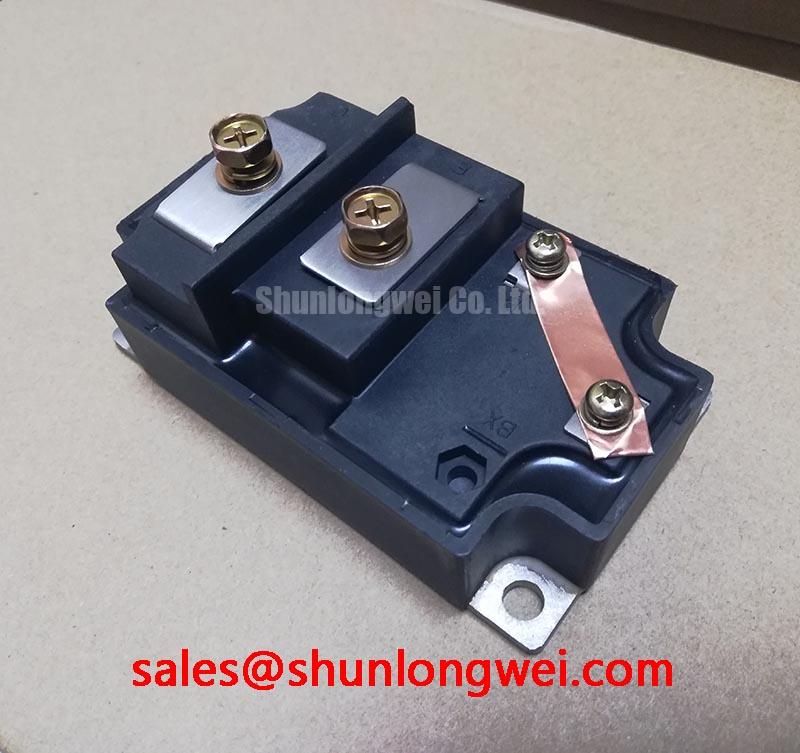
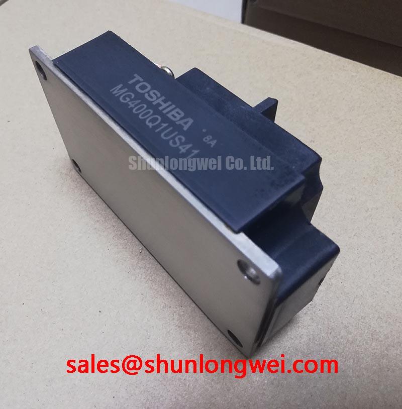
Engineered for high-power conversion, the Toshiba MG400Q1US41 IGBT module delivers robust performance by minimizing both conduction and switching losses. This device integrates a high-speed, free-wheeling diode to achieve a superior balance of efficiency and durability. Key specifications include: 1200V Collector-Emitter Voltage | 400A Collector Current | 2.7V VCE(sat) max. Its design provides two core engineering benefits: significantly reduced thermal load and enhanced reliability in demanding applications. This module directly addresses the challenge of designing efficient, high-current inverters by offering a low on-state voltage drop even at its maximum rated current. For industrial drives and high-power inverters requiring dependable performance, the MG400Q1US41 offers a well-defined path to achieving higher system efficiency.
Application Scenarios & Value
Achieving System-Level Efficiency Gains in Industrial Power Conversion
The MG400Q1US41 is optimally suited for high-power, high-frequency applications where energy efficiency is a primary design constraint. Its primary value is demonstrated in systems like industrial Variable Frequency Drives (VFDs), large-scale Uninterruptible Power Supplies (UPS), and induction heating systems. The engineering challenge in these applications is often managing the substantial heat generated from power losses. The MG400Q1US41 confronts this directly through its low collector-emitter saturation voltage (VCE(sat)) of 2.7V at 400A. This characteristic is analogous to having a water pipe with a very smooth inner surface; less energy is wasted as 'friction' (in this case, heat) when the current flows through. This directly reduces the power dissipated as heat, allowing for smaller, more cost-effective heatsink solutions and increasing overall system reliability. For applications requiring a higher current rating in a similar package, the related CM600DX-24T serves systems with greater power demands.
Key Parameter Overview
Decoding the Specs for High-Frequency Performance
The technical specifications of the MG400Q1US41 are tailored for robust performance in demanding power switching circuits. The table below highlights the critical parameters that enable its efficiency and reliability. The highlighted values underscore the device's capacity for high-power handling with minimized losses.
| Parameter | Symbol | Condition | Value |
|---|---|---|---|
| Collector-Emitter Voltage | VCES | VGE = 0V | 1200 V |
| Gate-Emitter Voltage | VGES | VCE = 0V | ±20 V |
| Collector Current (DC) | IC | Tc = 25°C | 400 A |
| Collector Power Dissipation | PC | Tc = 25°C | 2500 W |
| Collector-Emitter Saturation Voltage | VCE(sat) | IC = 400A, VGE = 15V | 2.7 V (Max) |
| Input Capacitance | Cies | VCE = 10V, VGE = 0V, f = 1MHz | 45000 pF (Typ.) |
| Turn-On Time | ton | Resistive Load | 2.0 µs (Max) |
| Turn-Off Time | toff | Resistive Load | 3.0 µs (Max) |
| FWD Reverse Recovery Time | trr | IF = 400A | 0.25 µs (Max) |
| Thermal Resistance (Junction to Case) | Rth(j-c) | IGBT | 0.05 °C/W (Max) |
| Isolation Voltage | VISOL | AC, 1 minute | 2500 Vrms |
Download the MG400Q1US41 datasheet for detailed specifications and performance curves.
Technical Deep Dive
The Engineering Impact of Fast Diode Recovery Time (trr)
While low VCE(sat) addresses conduction losses, the efficiency of a power system operating with IGBT modules heavily depends on minimizing switching losses. A critical parameter here is the reverse recovery time (trr) of the integrated free-wheeling diode (FWD), which is specified at a swift 0.25 µs for the MG400Q1US41. During the turn-off phase of the diode, it briefly conducts current in the reverse direction—a phenomenon that causes significant power loss and EMI noise. What is the primary benefit of its fast trr? It dramatically reduces the duration of this reverse current flow. This is like a valve that shuts off almost instantaneously, preventing backflow. In a Pulse Width Modulation (PWM) controlled inverter, this action repeats thousands of times per second. The cumulative effect of a fast trr is a substantial reduction in switching losses, enabling higher operating frequencies, which in turn allows for smaller, lighter, and more efficient magnetic components like inductors and transformers in the final system design. This is a crucial factor for achieving compliance with modern efficiency standards like those from Mitsubishi Electric for advanced servo drives.
Frequently Asked Questions (FAQ)
How does the 2.7V VCE(sat) at 400A impact thermal design choices?
A low VCE(sat) at high current directly reduces conduction power loss (P = VCE(sat) * IC). With a lower heat load to dissipate, engineers can specify a smaller, lower-cost heatsink or utilize higher ambient operating temperatures without exceeding the maximum junction temperature. This enhances system power density and can lower the total bill of materials.
What is the significance of the 2500V isolation voltage for system integration?
The integrated isolation simplifies the mechanical and thermal design of the power assembly. It allows multiple modules to be mounted on a single, non-isolated heatsink without needing external insulating pads, which often have poor thermal conductivity. This improves thermal transfer, reduces assembly time, and enhances the overall safety and reliability of the final product, a key consideration for standards like IEC 61800-5-1.
For which switching frequencies is the MG400Q1US41 most suitable?
Given its switching characteristics (ton, toff) and the fast recovery diode (trr), this module is well-suited for applications operating in the typical industrial frequency range of a few kHz up to approximately 20 kHz. It provides an excellent balance between low conduction losses and manageable switching losses in this range, making it ideal for motor drives and high-power inverters.
Strategic Outlook
The MG400Q1US41 is a strategic component for engineers developing next-generation power conversion systems that must meet increasingly stringent energy efficiency mandates. Its core design attributes of low on-state voltage and fast switching directly support the industry-wide push towards higher power density and reduced operational costs. By enabling more efficient energy use at the component level, this module serves as a foundational building block for creating more compact, reliable, and cost-effective high-power electronics. As designers contend with rising energy costs and environmental regulations, selecting components like the MG400Q1US41 provides a clear advantage in achieving both performance targets and long-term strategic business goals. For a broader understanding of IGBT selection, explore our guide on the core principles of voltage, current, and thermal management.