

Content last revised on September 10, 2026
Aluminum Heat Spreader Sizing & Thermal Interface Placement along Narrow Display Edges
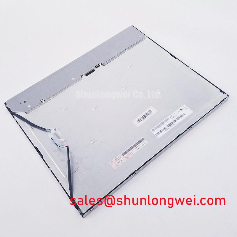
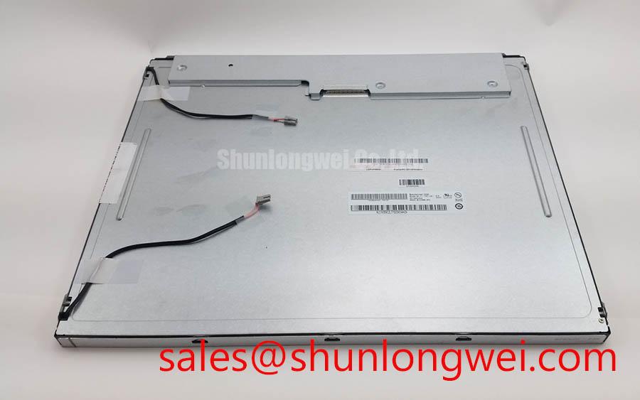
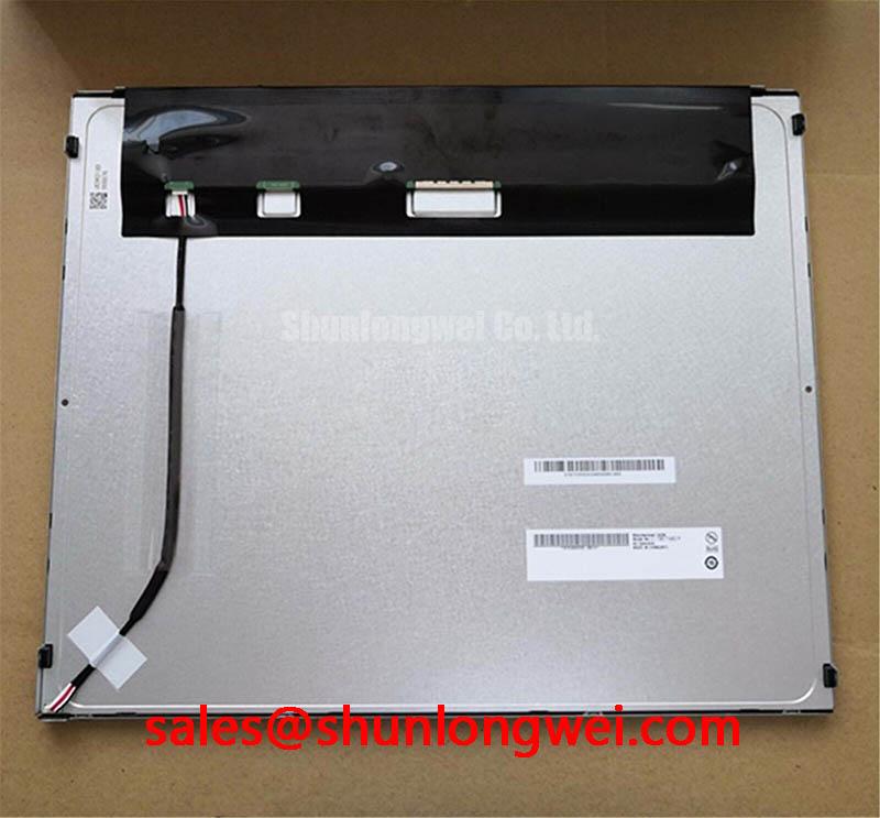
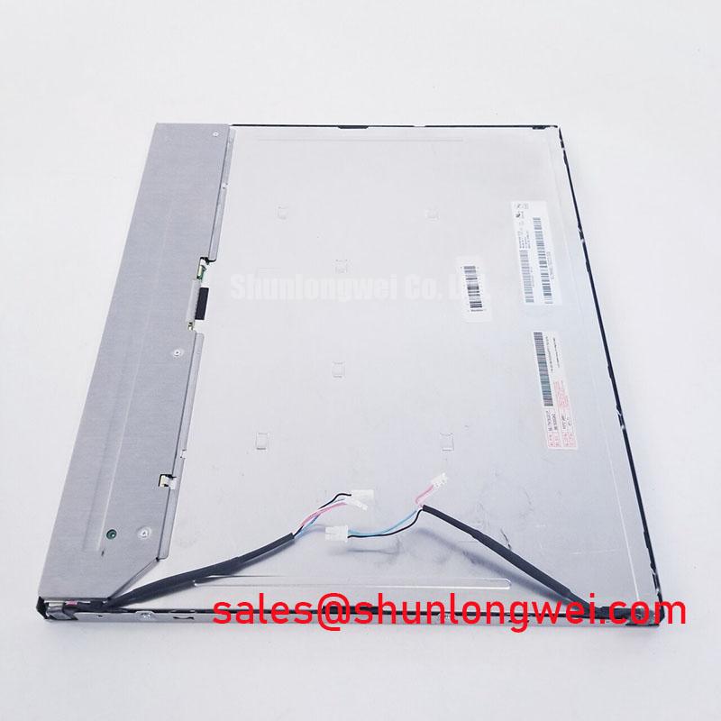
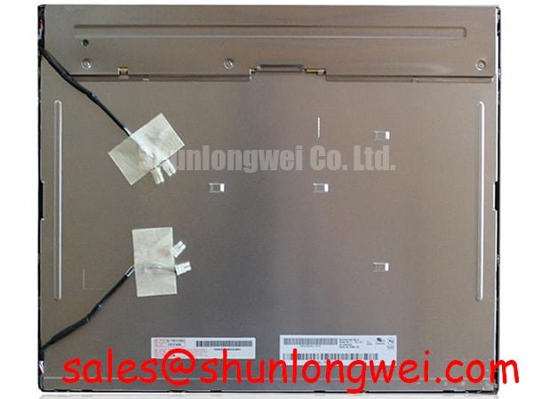
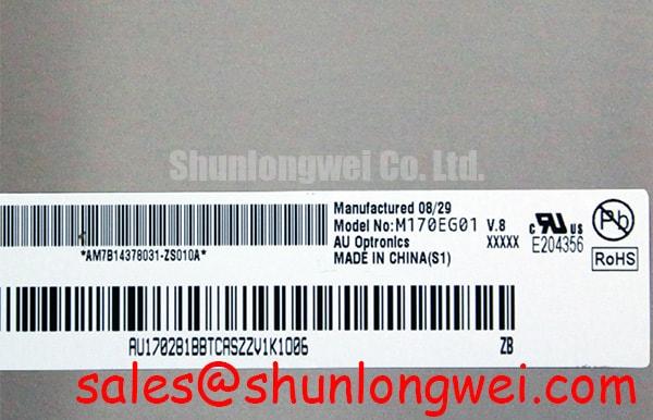
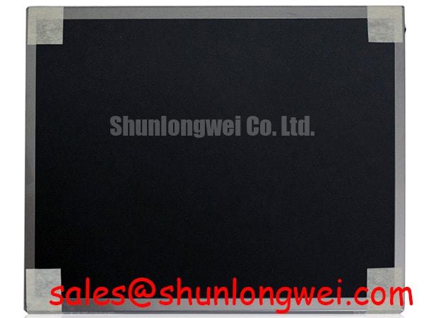
For a replacement display in a protection relay or SCADA dispatch console, begin with the mechanical envelope rather than adding thermal parts immediately. Record the existing bezel opening, rear clearance, mounting points, cable exit direction, and any metal rail that contacts the original display assembly. The M170EG01 V8 is identified in the supplied data as a TFT-LCD module, but the available factory information does not confirm an aluminum heat spreader requirement, edge rail geometry, LED life rating, PMMA optical material, or a specified thermal interface.
Design Consideration: A metal enclosure can create localized heat concentration near narrow display edges when internal power supplies, inverter hardware, or processor boards are positioned close to the panel. If thermal mapping shows a persistent hot area, the system designer may evaluate a mechanically isolated heat spreader or enclosure ventilation path. That assessment should preserve the panel’s flatness, avoid pressure on the active area, and prevent the spreader from contacting exposed conductors or the display flex.
Do not treat a proposed contrast ratio, sunlight performance value, anti-glare coating, or L70/B50 lifetime figure as an official specification for this model unless it appears in the original AUO documentation. The supplied product data does not verify a contrast ratio above 500:1 at 50,000 lux, a specific surface treatment, or a rated LED half-life. Optical acceptance should therefore be performed on the actual replacement panel under the intended enclosure lighting. Check white, black, red, green, and blue screens for nonuniformity, edge shading, contamination, and pixels that remain visibly different from the surrounding field.
When the display is used in a high-voltage substation protection or SCADA console, designers should also inspect the enclosure’s internal heat sources and airflow direction. The panel should not be used as a structural support for heavy boards, cable bundles, or a rear cover. If an external rail is considered, verify that it does not bend the frame or transfer enclosure distortion into the glass. A thermal solution is acceptable only after mechanical fit, optical uniformity, insulation spacing, and signal stability have been checked together.
Dynamic Contrast Ratio Stabilization & Liquid Crystal Birefringence Temperature Tracking
Incoming optical testing should be performed after the panel has reached a stable condition in the test fixture. Use full-screen test patterns and inspect the display from the intended operator position as well as from practical service angles. Look for grayscale inversion, color shift, flicker, image retention, and uneven brightness. The available factory record does not state whether this model uses TN, IPS, MVA, or another liquid-crystal mode, so a symmetric viewing specification of 85° in four directions must not be assigned to the unit without documentary confirmation.
Design Consideration: Liquid-crystal optical behavior can vary with temperature, viewing angle, drive timing, and the optical stack used by the panel. For a SCADA console, compare the replacement display with a known-good signal source using the same graphics mode, refresh configuration, and brightness setting. If grayscale transitions change as the enclosure warms or cools, record the condition and compare it with the original panel documentation rather than assuming a panel defect.
Interface compatibility requires the same discipline. The supplied information does not confirm TTL or LVDS signaling, connector pin assignment, pixel clock range, data hold time, supply voltage, backlight control method, or power sequencing. The system integrator should verify the required supply voltage and interface format from the original panel documentation. Do not connect a cable based only on connector appearance or a similar model code.
When a screen shows intermittent data, colored vertical lines, unstable synchronization, or a blank image, inspect the complete signal path. Check cable seating, latch engagement, ground continuity, controller output, and the timing configuration. An oscilloscope comparison with a known-good signal path may help identify impedance or timing irregularities, but the measured waveform must be assessed against the controller and panel specifications. A replacement panel should not be declared faulty until the cable, controller, power rail, backlight circuit, and display settings have been separately verified.
💡 Bench Tip: Use ESD protection and insert the display flex cable squarely before locking the connector; never force a cable that is entering at an angle.
Thermal Expansion Clearance Sizing across Heavy Industrial Metal Enclosure Cutouts
Mechanical inspection is especially important when the panel is installed behind a rigid metal fascia. Measure the opening and compare it with the original assembly before tightening any fasteners. The supplied factory data does not provide the outer bezel dimensions, mounting-hole coordinates, glass thickness, or approved fastener torque for M170EG01 V8. Those values must come from the original AUO mechanical drawing or the equipment service documentation.
Engineering Recommendation: Use the existing mounting method whenever it is mechanically compatible, and distribute clamping force evenly around the frame. Avoid using the display glass, polarizer surface, or connector edge as a datum for forcing alignment. If an enclosure has shifted after years of service, correct the enclosure first. Tightening a replacement panel into a distorted opening can introduce uneven frame loading and may produce pressure-related optical nonuniformity.
A cross-pattern tightening sequence can help distribute force, but the applicable torque remains system determined unless the manufacturer’s drawing specifies it. The commonly suggested M3 torque range of 0.35 to 0.45 N·m must not be presented as an AUO factory limit for this model. The equipment manufacturer may specify a different fastener, washer, spacer, thread engagement, or torque value. Confirm those details before final assembly.
After mechanical installation, run a dark-field test and then display uniform white and gray fields. Inspect the corners, edges, and areas close to fasteners for changes that appear only after the bezel is secured. If a defect changes when mounting pressure is released, treat the result as a mechanical integration issue requiring controlled inspection. Do not press the active area to “test” the symptom. The same inspection should include the flex cable bend radius, cable strain relief, connector locking position, and clearance from sharp metal edges.
For alternative hardware evaluation, engineers can compare the interface and mechanical documentation of M185XW01 VE. A different display cannot be treated as a direct replacement solely because its category or diagonal class appears similar. Resolution, active area, connector position, power requirements, timing, mounting geometry, and backlight control must all match the host equipment.
Dual-Channel CCFL High-Voltage Resonant Inverter Striking Voltage & Ignition Debugging
Do not assume that the M170EG01 V8 uses CCFL backlighting, LED backlighting, a dual-channel inverter, or a particular ignition voltage. None of those details is confirmed in the supplied factory parameter set. Before powering a replacement, identify the backlight architecture from the original panel documentation and the host equipment schematic. The system integrator should verify whether the existing controller requires a dedicated inverter, enable signal, dimming input, or a specific backlight supply.
If the original system contains a high-voltage lamp inverter, service personnel should treat the inverter output as a hazardous circuit and follow the equipment manufacturer’s discharge and isolation procedure. A cold-ignition value such as 1,500 to 1,650 Vrms must not be assigned to this AUO model without an authoritative specification. Inspect the inverter connector, lamp wiring, insulation, grounding path, and feedback circuit before attributing a dark display to the panel. Audible noise may arise from the inverter, mounting resonance, cable routing, or drive conditions, so the complete assembly requires evaluation.
If the equipment has been converted to an LED driver, verify the driver’s current regulation, enable logic, dimming method, connector pinout, and thermal behavior. A 1,000:1 PWM dimming ratio is not confirmed for this product and should not be used as a purchase or integration assumption. The replacement display and its controller must be tested at the brightness levels required by the operator interface, including startup, shutdown, low-brightness operation, and recovery after a control-system reset.
Low-temperature testing should focus on observable behavior: startup time, flicker, brightness stability, image response, cable reliability, and controller alarms. The supplied record does not specify an operating range of minus 20 to minus 30 degrees Celsius, a heater strip, GTG response time, or a backlight half-life. Those limits must be obtained from the applicable AUO documentation and verified within the host system’s environmental test plan.
For connector, timing, and optical troubleshooting, the engineering background in The Ultimate Guide to Industrial TFT-LCD Technology can be used alongside the original panel and controller documents. The product-level facts available for this listing remain the manufacturer, model, product category, TFT-LCD module construction, and official factory specification status. Final acceptance should be based on measured fit, image quality, interface operation, backlight behavior, and the documented requirements of the SCADA or protection-console assembly.