

Content last revised on September 13, 2026
Cold Start Verification for the M170EG01 VH in Industrial HMI Consoles
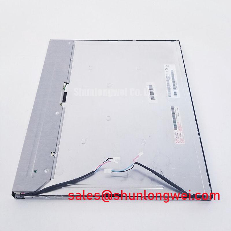
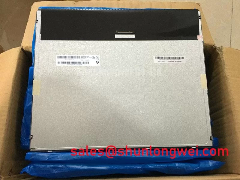
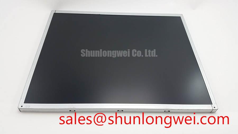
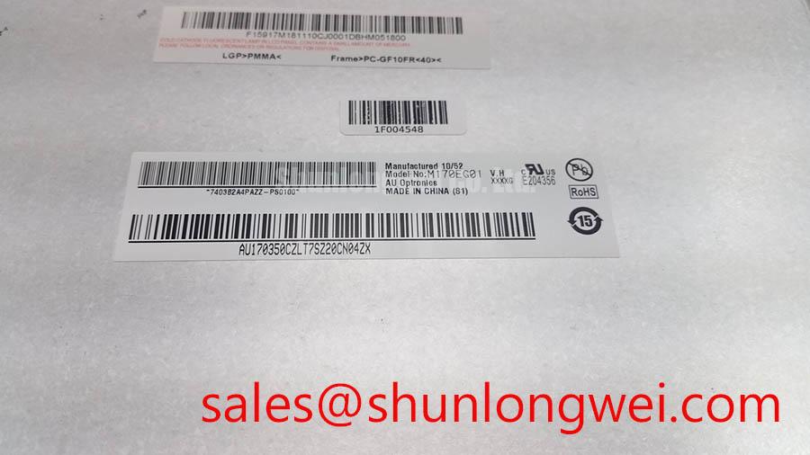
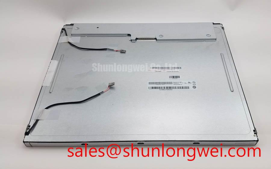
Begin a replacement check by comparing the installed panel label with M170EG01 VH, then inspect the display perimeter, connector area, mounting points, and visible sealing surfaces before applying power. This unit is identified as an AUO TFT LCD Display Module in the industrial-grade LCD and HMI panel category. The available factory specification context confirms the model identity and product class, but it does not establish every electrical interface, backlight characteristic, or mechanical drawing required for a direct system substitution.
For a high-voltage substation protection or SCADA dispatch console, record the original panel’s connector position, active display area, mounting-hole pattern, bezel opening, cable exit direction, and controller compatibility. A panel that matches the diagonal class can still require changes to the carrier bracket, display cable, timing controller, or front-panel aperture. The system integrator should verify the original panel documentation rather than infer interface details from the model name.
Cold-start behaviour should be evaluated as a system test rather than treated as an assumed characteristic of this display module. Liquid-crystal response can vary with temperature, while the host controller, cable assembly, and backlight circuit may introduce separate startup delays. When the console operates through a broad industrial temperature range, engineers should measure image appearance, synchronization, and backlight start-up at the actual equipment limits specified for the complete assembly. No specific response-time value or thermal operating range should be assigned to this model without the applicable AUO datasheet or panel revision documentation.
The same principle applies to perimeter sealants and enclosure materials. The display module should be installed within an enclosure whose sealing, condensation control, and thermal management have been validated by the equipment manufacturer. If the console is exposed to rapid temperature transitions, inspect for condensation and verify that the enclosure does not transfer mechanical stress into the glass or connector region.
Backlight control also requires identification of the original electrical arrangement. The supplied product information does not confirm whether the installed configuration uses a particular backlight technology, connector pinout, current requirement, or dimming method. The system integrator should verify the required backlight supply and control method from the original panel documentation. If PWM dimming is used by the host, its frequency, duty-cycle behaviour, conducted noise, and visual performance should be validated on the complete display assembly rather than assumed from a generic industrial display design.
When a same-class replacement is being considered, compare the complete mechanical and electrical interface before ordering. The M185XW01 VE may be reviewed as a separate display option during a structured substitution study, but it should not be treated as an automatic replacement for the M170EG01 VH. Resolution, active area, connector mapping, timing requirements, bezel dimensions, and backlight power must all be confirmed against the host equipment.
Viewing Direction, Grayscale Behaviour, and Front-Panel Alignment
Before removing a working panel from a protection or dispatch console, document the operator’s normal viewing direction and the screen angle relative to the enclosure. Viewing performance is affected by the panel technology, optical stack, cover window, surface treatment, and installation angle. The available factory information identifies the product as an AUO TFT-LCD module but does not provide verified viewing-angle, contrast-ratio, grayscale-response, or anti-glare values for this exact panel revision.
For a normally white display configuration, engineers should check whether grayscale transitions remain visually consistent from the actual operator position. Any apparent inversion, loss of detail, or brightness variation should be assessed with the original and replacement panels under identical image content and illumination. This is a comparative integration test, not evidence of a single internal fault. Ambient reflections from a console window or protective cover can also alter perceived contrast, so the test should include the final front-panel assembly.
The video interface must be confirmed from the panel documentation and controller board markings. Do not infer TTL, LVDS, JEIDA, VESA, bit depth, pixel clock, or signal polarity from the model number alone. If a digital interface is present, verify the transmitter format, lane or bus assignment, clock relationship, data hold behaviour, and cable orientation with the original electrical drawings. A connector that is physically compatible may still carry a different signal assignment.
During fault isolation, compare the replacement panel with a known-good signal path using an oscilloscope or suitable display test equipment. Look for unstable synchronization, intermittent image tearing, colour-channel displacement, or a failure that changes when the cable is moved. These observations may indicate a cable, connector, timing-controller, grounding, or configuration issue, so the investigation should include the host board and harness rather than attributing the symptom to the LCD glass immediately.
💡 Pro Tip: Keep high-speed display conductors consistently referenced to their return path and avoid unnecessary cable loops, then verify image stability on the assembled console rather than on an open bench setup.
For high-ambient-light installations, evaluate the final optical stack with the specified cover glass, bezel, protective film, and enclosure lighting. The supplied information does not verify a particular anti-glare etch, surface haze value, sunlight contrast ratio, or symmetric viewing cone for the M170EG01 VH. Those characteristics should be taken from the applicable panel revision documentation or measured using the finished front-panel construction.
Backlight and Connector Checks During Replacement Debugging
A dark screen does not by itself identify a failed LCD module. Start by separating the image path from the illumination path. With power removed, inspect the panel connector for bent contacts, contamination, mechanical stress, or incomplete insertion. Then confirm that the host controller is producing the expected image data and that the backlight control circuit is responding according to its own design documentation.
The available factory context does not confirm a dual-channel CCFL inverter, a constant-current LED driver, an ignition voltage, a dimming ratio, a rated optical half-life, or an MTBF value for this model. Such values must not be assigned to the M170EG01 VH without a matching AUO specification sheet. If the original console contains a separate inverter or backlight driver, identify that assembly independently and check its input, enable, dimming, protection, and output characteristics against the equipment service documentation.
For a suspected backlight issue, compare the panel’s image data path with a controlled external light source or a suitable optical inspection method. A faint image can suggest that the image-generation section is active while illumination is not, but the result may also involve the inverter, driver, enable signal, cable, or power rail. Confirm the measurement points and allowable limits from the original design before applying probes to a high-voltage lighting circuit.
Acoustic noise should be investigated at the driver and enclosure level. Resonance from an inverter, transformer, fan, bracket, or cover can be transmitted through the console and may change with brightness or dimming commands. Do not use an assumed PWM frequency or duty-cycle range as a product specification. Instead, capture the control waveform and compare it with the driver manufacturer’s documented requirements, checking that the selected operating point does not create visible flicker, audible excitation, or unwanted interference in the display signal.
When a screen is replaced in a SCADA dispatch console, preserve the original cable routing and strain relief during the initial test. After the image, backlight, and controls have been confirmed, inspect the panel under the final enclosure pressure and temperature conditions. A panel that operates correctly outside the console may show intermittent behaviour after the bezel, gasket, cable bend, and rear cover are reinstalled.
⚠ Safety Interlock Note: Disconnect equipment power and allow the relevant backlight or inverter circuit to discharge before removing or inserting display cables.
Digital RGB or Serial Interface Verification and Logic Power Review
Verify the panel logic supply at the connector against the original AUO documentation before connecting the M170EG01 VH to a controller. The supplied factory information does not confirm whether this model revision requires a specific logic voltage, nor does it provide a validated power-on rise-time window, interface mapping, or connector pin assignment. The system integrator should verify the required supply voltage from the original panel documentation rather than selecting between common display voltages by assumption.
Power sequencing should be checked with the panel, controller, backlight driver, and cable connected in their normal configuration. Observe the logic rail, display-enable signal, reset or standby control, and video clock relationship using test equipment appropriate to the system. If the image starts only after repeated power cycles, investigate sequencing, brownout behaviour, controller firmware, connector contact quality, and cable integrity together. A startup symptom does not establish a single cause.
If the host uses a parallel digital RGB bus, confirm the number of data bits, pixel-clock edge, sync polarity, blanking requirements, and JEIDA or VESA mapping from the original panel specification. If the host uses a serial differential interface, confirm lane assignment, polarity, termination, cable orientation, and transmitter compatibility. These formats are not interchangeable merely because the connector appears similar. Where differential signalling is used, routing should maintain a controlled return path and avoid avoidable discontinuities; the final design team must determine the appropriate impedance and verify signal quality on the installed harness.
Split-screen images, colour swaps, unstable vertical structure, or a shifted picture should be examined against the known-good controller configuration. Check mapping first, then timing, cable orientation, clock quality, and power stability. A logic analyser or oscilloscope can help compare the clock and data relationship, while a direct visual comparison can reveal channel-order or polarity errors. Record the panel revision and controller firmware version because a configuration that works with one display revision may not apply to another.
The M170EG01 VH is listed as an industrial-grade LCD/HMI panel with a TFT-LCD display module construction and AUO manufacturer identification. Its suitability for a particular high-voltage substation protection or SCADA dispatch console depends on verified interface, mechanical, optical, environmental, and backlight compatibility. Engineers evaluating enclosure sealing, thermal transfer, vibration control, and service access can also consult the Industrial Display & HMI Solutions engineering reference.
For procurement and repair records, retain the exact model marking, panel revision, connector photographs, controller part number, and the original equipment documentation. These records allow the replacement assessment to remain tied to confirmed hardware information instead of generic assumptions about display technology.