

Content last revised on October 22, 2026
M170EG01-V2 Identification and Installation Checks
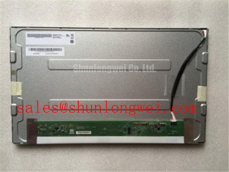
- Disconnect equipment power and compare the M170EG01-V2 label, connector orientation, and mounting features with the removed display assembly.
- Inspect the bezel, gasket contact surfaces, mounting supports, and cable exits for uneven compression or trapped wiring.
- Check the display harness and connector locks before reconnecting the controller or backlight power circuit.
- Record the existing image defect, brightness setting, and enclosure temperature so that subsequent checks use comparable conditions.
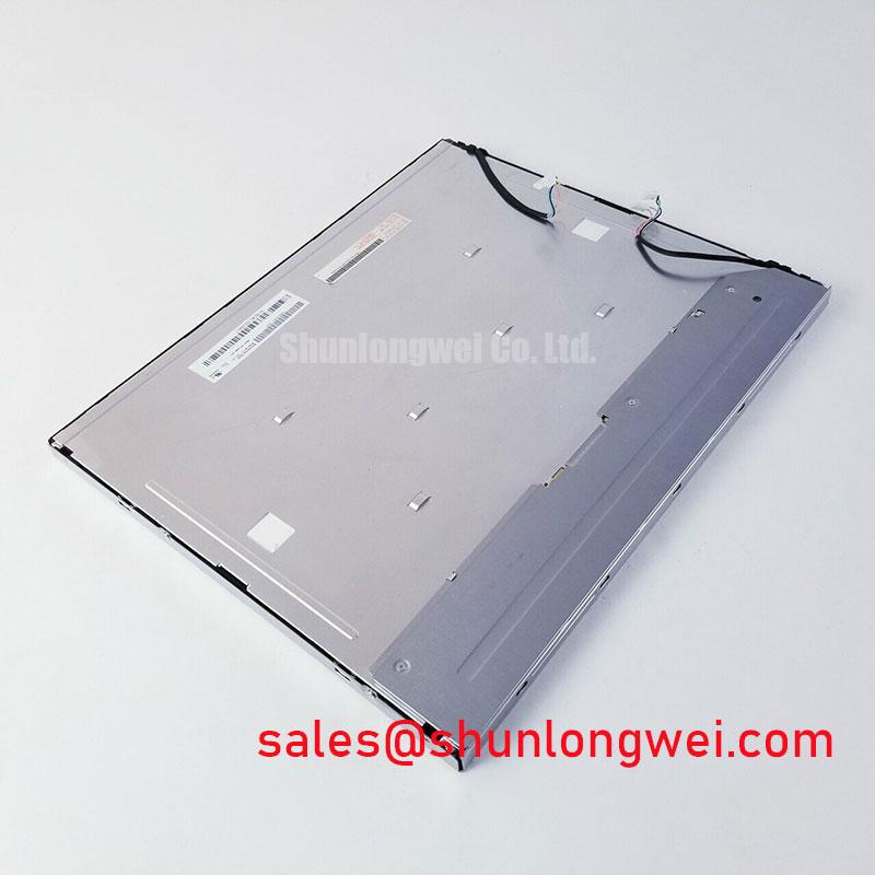
The M170EG01-V2 is an AU Optronics TFT-LCD active-matrix color display module considered here for industrial LCD/HMI evaluation. Replacement assessment should separate the panel itself from the enclosure, controller, harness, and backlight power assembly: a mechanically compatible installation still needs electrical and optical compatibility checks.
| Product identification | Baseline information |
|---|---|
| Model | M170EG01-V2 |
| Manufacturer reference | AU Optronics (AUO); match the model and revision to the module label and original documentation. |
| Product category | LCD panel; suitability for industrial HMI use requires system-level assessment. |
| Module construction | TFT-LCD active-matrix color display module |
| Electrical, optical, and dimensional ratings | Consult the model-specific datasheet for supply voltage, interface, pin assignment, backlight requirements, outline dimensions, resolution, brightness, and temperature limits. |
Chassis Fastener Torque Sizing and Optical Mura Control
Check that the mounting supports contact the display assembly evenly before tightening the bezel. Design Consideration: a distorted bracket, an incorrectly seated gasket, or a fastener bottoming out can introduce uneven loading around the display perimeter. Localized pressure can change image uniformity, but a bright patch or dark region alone does not establish a mechanical cause.
Compare the assembled display with a mechanically relaxed inspection condition, keeping the brightness setting, displayed pattern, and viewing position unchanged. Use uniform dark and midtone images to observe whether a defect changes with enclosure loading. Support the module securely throughout the comparison; do not press the viewing surface to reproduce a symptom. Record whether the affected area follows a mounting location or remains fixed regardless of the bezel condition.
Fastener torque belongs to the complete joint specification. Thread engagement, bracket material, inserts, washers, and gasket compression all affect the suitable tightening limit. A generic screw-size torque should not become an M170EG01-V2 installation rating. Engineering Recommendation: use the equipment assembly drawing to establish the fastening sequence and torque, then check optical uniformity after the enclosure is fully assembled.
Gasket fit deserves the same attention as the mounting hardware. The seal should follow its intended contact path without rolling into the active viewing area or forcing the panel against an uneven support. Keep sealing loads on the intended enclosure surfaces. A compressed gasket is not, by itself, evidence of a dust-tight assembly; enclosure sealing depends on the complete mechanical design.
Inspect flexible cable routing while the rear cover is accessible. A cable trapped beneath a bracket can transfer force into its connector as the cover is tightened. Provide strain relief through the intended chassis features rather than through the connector latch, and avoid repeatedly folding the flex at the same location. Cable bend radius and flex endurance should follow the cable assembly specification.
Maintenance Note: Periodically inspect cooling passages and gasket seating with equipment power disconnected, without disturbing the display connector or applying pressure to the viewing surface.
For dimensional comparison, the M185XW01 V7 can be reviewed as a separate candidate, not an assumed replacement. Compare mounting locations, active-area position, outline, connector access, controller timing, and backlight compatibility before considering any substitution.
Optical Luminance Degradation and CCFL-to-LED Retrofit Assessment
Measure brightness under repeatable conditions before deciding that the display needs a backlight retrofit. Design Consideration: apparent dimming can involve the light source, its power circuit, the optical path, surface contamination, or controller settings. Comparing measurements at different brightness commands or temperatures can obscure the actual change.
Use the same test image and ambient-light conditions when checking the M170EG01-V2 assembly. Record center brightness and visible spatial uniformity after stabilization. If the image is present but poorly illuminated, investigate the backlight power and control path separately from the video path. Intermittent illumination warrants connector and supply checks before attributing the problem to light-source aging.
A CCFL-to-LED conversion is a system modification rather than a connector-only repair. Where such a conversion is being evaluated, compare mechanical clearance, illumination distribution, heat dissipation, control polarity, startup behavior, and fault handling. These are retrofit assessment criteria, not a declaration of the backlight fitted to this model. Preserve the original assembly identification so that the conversion remains distinguishable from the baseline panel configuration.
For a proposed constant-current LED driver, assess efficiency at the intended operating load and enclosure temperature. Input power that does not reach the light source becomes heat elsewhere in the assembly. A replacement driver therefore needs thermal assessment in its installed position, including surrounding wiring and restricted airflow, rather than an efficiency comparison made only on an open bench.
PWM dimming should be evaluated for visible flicker, brightness consistency, camera banding where relevant, and interaction with the controller. Frequency alone does not establish flicker-free operation. The appropriate control method depends on the driver, light source, duty-cycle behavior, and equipment requirements. Acoustic noise should likewise be investigated across operating states rather than assigned automatically to a particular backlight technology.
Luminance maintenance and MTBF describe different things: a brightness-degradation criterion does not establish a complete display assembly’s failure interval. Use defined measurement conditions and the relevant manufacturer qualification evidence when comparing either claim. The Ultimate Guide to Industrial TFT LCD Technology provides broader context for separating display selection criteria from system-level operating assumptions.
Surface Anti-Glare and Anti-Reflective Treatment for Ambient Readability
Examine reflections at the actual operator viewing position before changing brightness or adding a surface film. Design Consideration: readability depends on ambient illumination, viewing direction, front-window reflections, image contrast, and display settings together. Increasing backlight output cannot remove every reflection introduced by the enclosure window.
Anti-glare and anti-reflective treatments address different optical effects. Anti-glare surfaces redistribute reflected light, while anti-reflective treatments reduce reflection through their optical design. Neither treatment should be assigned to the M170EG01-V2 without its optical specification. An aftermarket overlay also changes the complete viewing stack and should be assessed for haze, text sharpness, cleaning compatibility, and fit.
Check small text, alarm colors, and grayscale steps from the intended viewing positions. Changes with viewing angle should be documented rather than corrected by assuming a particular liquid-crystal operating mode. The explanation of In-Plane Switching panel technology is useful background for understanding viewing-angle behavior, but it does not establish that this module uses IPS. Likewise, the AU Optronics display portfolio provides manufacturer context, not model-specific qualification evidence.
Temperature assessment should distinguish a slow image transition from an unstable video signal. Liquid-crystal response can become slower as temperature falls, producing visible trailing even when the transmitted image remains stable. Evaluate transitions within the panel’s documented operating range and compare them with the equipment’s readability requirements. Heater integration, where required by the equipment design, needs separate thermal control and validation rather than being treated as a standard panel accessory.
Condensation control starts with the enclosure environment. When equipment moves between substantially different temperatures, moisture can form on surfaces below the local dew point. Allow environmental stabilization and inspect for moisture before energizing the assembly. Avoid directing concentrated heat at the panel to accelerate recovery, since uneven heating introduces another mechanical and optical variable.
For long-duration static interfaces, consider screen blanking or modest interface movement where the control system permits it. Persistent image retention should be assessed with changing content and repeatable observation conditions; it should not immediately be classified as permanent damage.
Suppressing Pixel Jitter and Horizontal Lines Near Motor Drives
Compare the display symptom with motor-drive operating states before modifying the signal harness. Design Consideration: pixel disturbance near switching equipment can involve interference coupling, supply instability, connector intermittency, controller timing, or the display assembly. Correlation with acceleration or braking helps structure the investigation but does not identify the faulty part by itself.
When evaluating the M170EG01-V2 for a factory automation machine-tool HMI operator terminal, compare the original controller output, harness construction, mounting arrangement, and environmental limits as one compatibility assessment. Cable routing should keep the display signal path away from high-current switching conductors where the enclosure layout allows, without compromising protective bonding or service access.
Establish the actual interface before selecting measurement techniques. For an LVDS link, evaluate differential signal quality, common-mode behavior, clock relationship, and receiver timing against the applicable transmitter and receiver specifications. For another documented interface, use its corresponding electrical requirements. Do not derive pin assignments, voltage levels, or termination values from connector appearance.
Clock jitter and data timing require attention at the receiving end of the installed harness. If temperature-dependent faults occur, compare waveforms and supply behavior across the equipment’s qualified operating conditions. The acceptance limits should come from the interface components and controller timing specification, not from a generic industrial-display rule.
Inspect shield continuity and chassis termination against the equipment grounding drawing. A shield that is electrically continuous can still have an ineffective high-frequency termination. Where the design uses a circumferential shield connection, check that enclosure reassembly has not disturbed it. Additional suppression components should be evaluated through controlled measurements; an arbitrary ferrite installation can alter the signal path without resolving the coupling mechanism.
Finally, inspect connector retention with power removed, then repeat the original operating sequence after reassembly. Keep the displayed pattern, harness position, brightness setting, and drive activity consistent. Record whether the disturbance changes after each intervention so that a quieter image is supported by a reproducible test rather than by a single successful restart.