Content last revised on October 30, 2026
LTM170E5-L03 Replacement Checks and Key Specifications
- Isolate power, then compare the panel label and connector orientation with the removed LTM170E5-L03 before connecting the display harness.
- Inspect the LVDS cable retention, contact condition, and routing for abrasion or tension at the connector.
- Check bezel clearance, gasket seating, and mounting supports for uneven pressure against the display assembly.
- Confirm that the controller supplies the specified panel logic voltage and that the separate CCFL inverter connections match the equipment wiring.
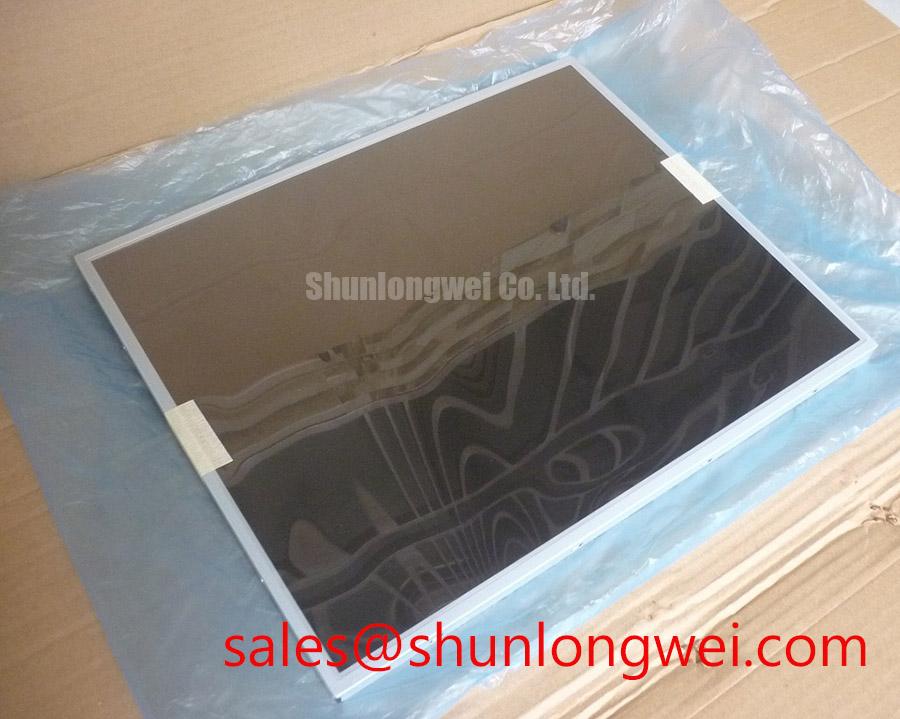
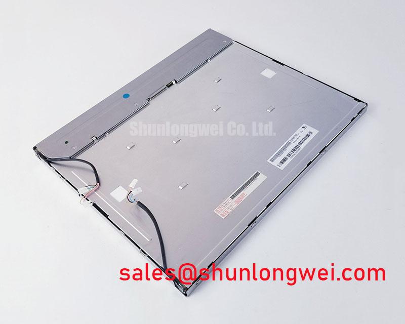
The LTM170E5-L03 from Samsung is a 17.0-inch a-Si TFT-LCD with SXGA resolution, a dual-channel LVDS interface, and CCFL illumination. For replacement assessment, distinguish the panel’s electrical requirements from the controller configuration, inverter behavior, and enclosure fit.
| Parameter | Official Specification |
|---|---|
| Panel size and technology | 17.0 inch, a-Si TFT-LCD |
| Resolution | 1280 (RGB) × 1024 pixels, SXGA |
| Active area | 337.92 × 270.336 mm |
| Typical luminance | 300 cd/m² |
| Typical contrast ratio | 800:1 |
| Display colors | 16.7 million, 8-bit |
| Signal interface | LVDS, 2 channels, 8-bit |
| Typical input voltage | 5.0 V |
| Backlight | 4 CCFL lamps |
| Refresh rate | 60 Hz |
Replacement-specific details requiring the original panel drawing and datasheet include connector pin assignments, data mapping, power sequencing, operating temperature limits, outer dimensions, mounting hardware, and tightening limits.
VESA vs. JEIDA Data Mapping Alignment & Even/Odd Channel Signal Integrity
Compare the controller’s LVDS bit allocation and channel assignment with the panel pinout before changing firmware or replacing the cable. Design Consideration: VESA and JEIDA mappings arrange color significance differently; matching connector geometry alone does not establish compatibility. Incorrect mapping can produce incorrect shades, while channel-order or timing problems can contribute to alternating-column errors or a divided image.
Use color ramps, primary-color fields, and alternating-pixel patterns to separate mapping errors from intermittent transmission faults. Check both LVDS channels rather than treating an acceptable image on one portion of the screen as proof that the complete link is sound. The specified 1280 × 1024 at 60 Hz is the display target, not a substitute for matching the controller’s complete output timing.
The panel logic supply is 5.0 V typical; this is distinct from inverter power. As an Engineering Recommendation, capture supply rise, data enable, backlight enable, and shutdown behavior together. Compare their order with the required sequence, including power removal, when investigating white screens or shutdown remnants. Avoid feeding active signal lines into an unpowered panel.
For backlight adjustment, evaluate the installed inverter’s supported dimming method and response. If it accepts PWM, the system designer should establish frequency and usable duty-cycle range from inverter requirements and measured flicker behavior; neither is established by the panel’s refresh rate.
Mitigating Gray-to-Gray (GTG) Response Time Escalation during Cold-Start Machine Power-Up
Compare moving gray transitions at cold start with the same patterns after thermal stabilization, keeping image content and backlight settings consistent. Design Consideration: liquid-crystal switching generally slows as temperature falls, so motion trails need to be distinguished from transmission errors and delayed illumination. This physical behavior does not establish a sub-zero operating rating for this panel.
The amorphous-silicon technology background explains the semiconductor technology identified by a-Si. The separate TFT LCD technology reference describes active-matrix addressing. Neither reference establishes this model’s gray-to-gray response time, viewing-angle mode, or environmental qualification.
When equipment moves between cold storage and a warmer workspace, allow enclosure conditions to stabilize before energizing moisture-sensitive assemblies. Inspect gasket continuity and moisture entry paths rather than assuming that a clear front window means the connector compartment is dry. Any environmental testing should remain within the panel’s documented limits.
Evaluate grayscale ramps after stabilization before adjusting controller gamma settings. Uneven tonal steps can involve source settings, reference-voltage behavior, or panel condition; they do not identify a single failed circuit. For persistent interface graphics, consider screen blanking or content variation during idle periods, then assess any residual image using a repeatable neutral pattern rather than assuming permanent damage.
Eye-Diagram Voltage Margin & Differential Noise Floor Verification in High-Vibration Bays
Probe the LVDS link near the receiving end and compare waveform quality with the equipment stationary and operating under its normal vibration conditions. Design Consideration: differential amplitude, common-mode behavior, clock jitter, and data timing should be judged against transmitter and receiver requirements, using a probing arrangement that does not materially load the link.
Intermittent pixel errors or horizontal interference can involve connector movement, cable damage, reference discontinuities, or coupled noise. Inspect harness support and shield termination before adding suppression parts. Preserve pair geometry and minimize discontinuities; cable impedance and skew acceptance belong to the complete link design, not an assumed panel-specific rule.
Where motor-drive switching is present, compare display disturbances with operating events and cable placement. Shield bonding or common-mode suppression may be evaluated as system-level measures, but their benefit needs measurement. They are not included panel features or evidence of equipment EMC compliance. The broader Industrial Display & HMI Solutions guidance provides context for enclosure, grounding, and maintenance decisions.
Industrial Bezel Mechanical Envelope Tolerances & Mounting Screw Torque Optimization
Check the chassis opening and mounting supports against the panel drawing before tightening fasteners. The 337.92 × 270.336 mm active area describes the visible image region, not the outer mechanical envelope. Design Consideration: support the assembly without forcing it flat against a distorted frame, and distribute tightening progressively using the documented hardware limits.
Compare dark and uniform-gray images before and after final assembly. A change in localized shading may indicate mounting stress or bezel contact, but optical nonuniformity also requires comparison with the panel outside the enclosure. Gaskets should seal the intended enclosure surfaces without transferring concentrated pressure into the display face.
For a marine radar or navigation bridge console replacement assessment, engineers should evaluate daylight readability, condensation control, and enclosure protection separately; 300 cd/m² typical luminance does not establish sunlight readability or salt-mist suitability. Optical bonding is an integration process requiring material and assembly validation, not an inherent moisture barrier provided by this panel.
Maintenance Note: Periodically inspect cooling passages and gasket seating so restricted airflow or displaced seals do not undermine the display installation.
After closing the bezel, check illumination uniformity across the brightness range and inspect inverter ventilation and cable clearance. If flicker or audible noise changes with dimming, assess inverter control behavior alongside lamp operation before attributing the symptom to mechanical pressure.