
Content last revised on October 12, 2026
Flush-Mount Open-Frame Bezel Integration & Perimeter Gasket Shock Isolation
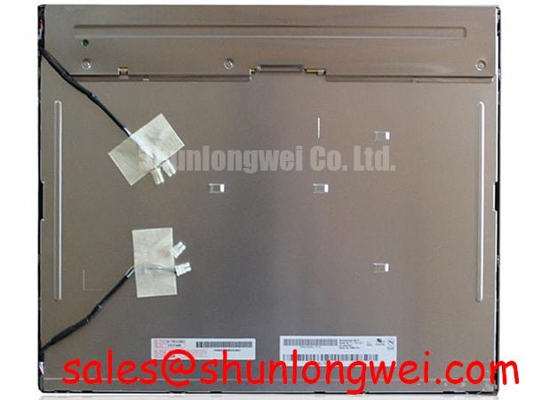
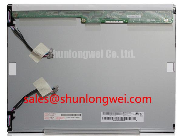
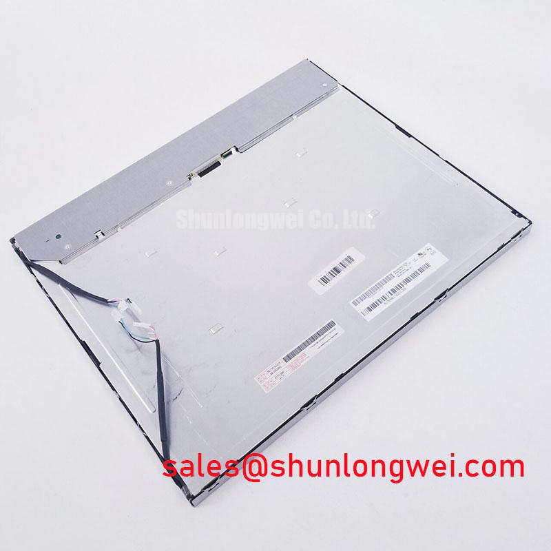
I compare a dark-gray image before and after bezel installation to check whether mounting pressure introduces edge shadows or uneven illumination. For the M170EG01-VA LCD display, the enclosure assessment should begin with the panel outline, mounting features, connector clearance, and the relationship between the bezel opening and visible image area. A familiar outline alone does not establish mechanical interchangeability.
Design Consideration: distribute enclosure loads through the intended mounting features rather than through the display face or cable exit. Evaluate perimeter gasket compression against the enclosure drawing and gasket supplier’s guidance. Tighten fasteners progressively in a cross pattern where the mounting arrangement permits, using the assembly-specific torque requirement. Compare the image after each assembly stage; pressure-related changes are evidence to investigate, not proof of a particular internal defect.
Leave sufficient cable clearance for the connector latch to close without the enclosure pushing against it. Route the flexible cable so that assembly movement does not concentrate bending at the connector termination. For vibration assessment, inspect cable restraint and connector retention before and after the equipment’s qualification test. Neither a gasket nor a secured cable establishes a vibration rating for the panel.
When reviewing repair candidates, compare the TX17D02VM2CAA-2 documentation against the original assembly’s dimensions, interface, optical requirements, and mounting geometry. Treat it as a separate comparison candidate, not an established substitute. Engineers evaluating an AGV operator display or forklift telematics screen should also assess enclosure support, operator sightline, and cable movement within that particular installation.
Dynamic Contrast Ratio Stabilization & Liquid Crystal Birefringence Temperature Tracking
Disable host-side automatic brightness and contrast adjustments before comparing grayscale uniformity, so that changing image processing does not obscure the panel’s optical behavior. Use identical image patterns and ambient lighting for each inspection. Record the brightness setting, observation position, and warm-up condition alongside photographs; otherwise, apparent differences between panels can reflect the test setup rather than the display.
Design Consideration: liquid-crystal response changes with temperature, and viewing direction can alter perceived contrast and grayscale separation. Examine dark gradients and small text from the actual operator position, then repeat from nearby positions. The explanation of viewing-angle characteristics in LCDs helps distinguish directional appearance from image uniformity. Do not assign TN, IPS, MVA, symmetric viewing-angle limits, or an anti-glare treatment to this model without its specification.
For cold-start evaluation, compare the first displayed frames with the stabilized image while keeping the enclosure within its qualified operating conditions. Slower transitions can affect moving symbols and text readability; response compensation belongs to the controller configuration and requires validation with the actual panel. Temperature-dependent appearance should not be interpreted as permanent damage from a single observation.
Long-lived static HMI elements deserve a separate retention check. Display a representative interface, then switch to a uniform background and observe whether a residual pattern changes during subsequent operation. As an Engineering Recommendation, interface designers can consider blanking idle screens or varying persistent graphics where operational requirements permit. These measures do not establish a model-specific retention guarantee.
Optical bonding should be assessed as an enclosure integration process, including stress, reflections, and serviceability. It does not independently establish moisture sealing. The manufacturer’s industrial display portfolio provides broader context, while the fitted panel’s optical acceptance criteria remain specific to its documentation.
Digital Video Interface Synchronization & Logic Power Rail Verification
Match the connector pin assignment to the controller schematic before evaluating clock timing or color mapping. The TTL wording in this section is an interface review topic, not confirmation that M170EG01-VA accepts a TTL bus. Establish the actual signal interface first; TTL timing and LVDS differential measurements are different checks and should not be applied interchangeably.
Design Consideration: capture logic power, interface activity, display enable, and backlight enable during startup and shutdown using an appropriately referenced measurement setup. Compare their order and transitions with the panel and controller requirements. Investigate a white screen or a lingering shutdown image by checking the complete sequence rather than attributing the symptom immediately to the LCD.
For a confirmed parallel interface, compare data setup and hold behavior with the receiver requirements at the panel connector. For a confirmed differential interface, assess pair routing, termination, clock quality, and cable continuity against the transmitter and receiver specifications. Check JEIDA or VESA mapping only where the documented interface requires it. Incorrect mapping can affect colors or image structure, but similar symptoms can also arise from timing or controller configuration.
Backlight enable and brightness control require their own schematic review. Observe brightness changes across the supported control range and check for visible modulation or audible noise under the intended operating conditions. Any dimming frequency and duty-cycle limits must come from the matched driver and display specifications. The TX18D35VM0APB-2 display documentation can support comparison of another display arrangement; it should not be treated as a backlight driver or accessory for this panel.
Incoming Benchtop Inspection: COG/TAB Anisotropic Conductive Film (ACF) Integrity
Run full-screen red, green, and blue patterns, then inspect white, black, and intermediate gray fields for persistent pixel defects, lines, edge shadows, and brightness variation. Keep the test image unscaled where the controller permits, and record defect locations relative to the active image rather than the bezel. Use the applicable purchasing acceptance criteria instead of inventing a universal allowable defect count.
Design Consideration: COG, TAB, and ACF describe display interconnection technologies, but the heading does not establish this panel’s internal construction. A persistent line warrants checking the image source, cable seating, and controller settings before assigning an internal cause. Compare with a known-good signal path where practical, and avoid pressing the panel edge to provoke or temporarily suppress a symptom.
💡 Bench Tip: With power disconnected and ESD controls in place, seat the display cable squarely and close its locking mechanism without pulling on the flexible tail.
For a dark screen, oblique external illumination can help determine whether an image remains faintly visible. Follow that observation with separate checks of image signaling and illumination power; the flashlight test alone cannot locate the failed part. Assess brightness and color uniformity at fixed settings, and retain photographs under consistent exposure.
For environmental integration checks, the Industrial Display & HMI Solutions guide provides broader engineering context rather than a panel qualification standard. Finish the acceptance record with connector condition, test configuration, optical observations, and repeat-test results so that a later technician can reproduce the inspection.