
Content last revised on September 26, 2026
Temperature-Dependent Image Response and Connector Stability
| Official Specification | AUO G156HAB01.0 |
|---|---|
| Product category and display technology | LCD display, AHVA mode |
| Screen diagonal and active area | 15.6 inches; 344.16 × 193.59 mm |
| Native resolution and aspect ratio | 1920 × 1080 pixels; 16:9 |
| Luminance and contrast ratio | 300 cd/m²; 800:1 |
| Viewing angles, left/right/up/down | 85° / 85° / 85° / 85° |
| Touch technology | On-Cell PCAP; 10-point multi-touch |
| Touch controller and signal interface | EETI 3200; USB |
| Cover glass | 7H hard coating; 1.1 mm soda-lime glass |
| Display signal interface | eDP 1.2; 2 lanes; 40-pin connector |
| Logic supply and maximum logic power | 3.3 V; 0.8 W maximum |
| Module weight and maximum depth | 620 g; 4.9 mm maximum |
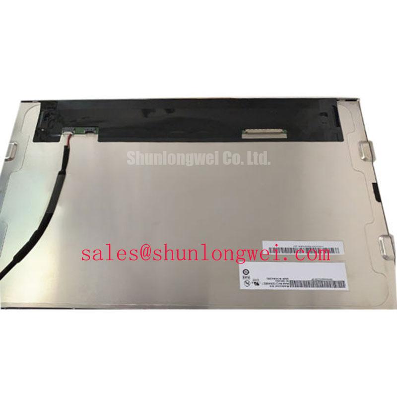
Display moving grayscale patterns and record panel temperature when investigating image trails, delayed transitions, or intermittent picture loss on the G156HAB01.0. Keep the source image, controller configuration, and camera exposure consistent between observations. A stationary photograph can reveal a defective pixel or an uneven patch, but it cannot establish transition performance. Record whether the symptom affects the entire image, follows particular gray transitions, or appears only when the equipment enclosure has warmed up.
Design Consideration: liquid-crystal response can slow as temperature falls, while connector contact problems and supply disturbances can produce superficially similar complaints. Separate these mechanisms by comparing moving-image behavior with static color fields and simultaneous supply measurements. The specifications above do not establish an operating-temperature range or a guaranteed gray-to-gray response time. Temperature qualification therefore needs the applicable AUO limits and the equipment acceptance procedure, rather than an assumed industrial temperature window.
For incoming inspection, run full-screen white, black, red, green, and blue images at native resolution. Inspect the active area for persistent bright points, dark points, clusters, and localized discoloration. Record defect coordinates relative to a consistent corner and retain photographs under controlled ambient lighting. Pixel acceptance should follow the agreed inspection criteria; the resolution specification alone does not define how many pixel defects are acceptable.
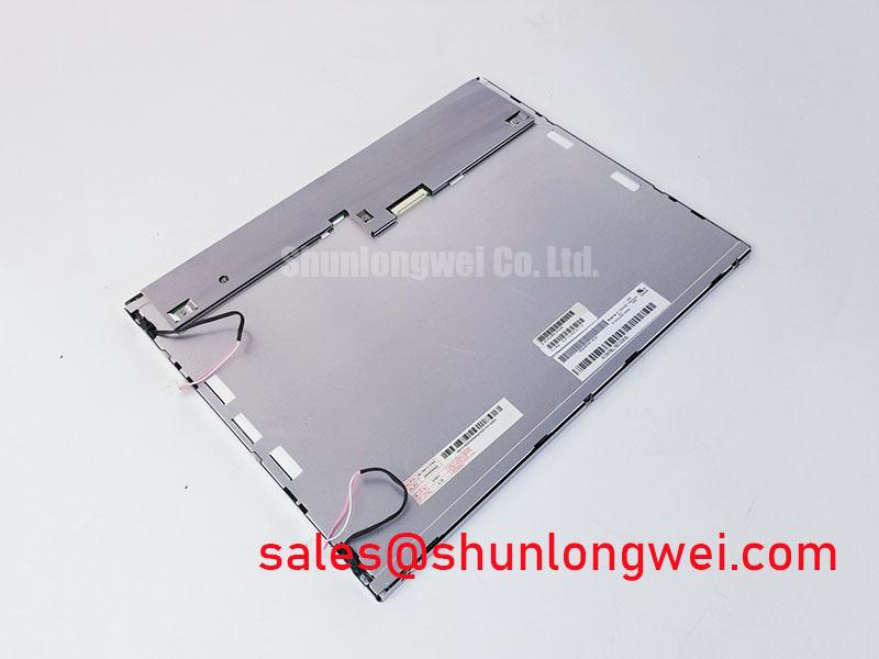
Design Consideration: when intermittent faults correlate with temperature, inspect the accessible connector, cable restraint, and frame attachment without disturbing the panel stack. Compare the image while the harness remains stationary and while its external strain relief is gently checked. A repeatable change is evidence worth investigating, not proof of a particular internal failure. Do not infer sealant chemistry, bonding construction, or thermal-cycle endurance from the module outline.
The 4.9 mm maximum depth and 620 g weight are official mechanical specifications, not a complete mounting drawing. Designers should verify attachment locations, connector clearance, and cover-glass clearance against the assembly drawing. Avoid transferring enclosure bending loads into the display face. For broader context on display response, integration, and common reliability assumptions, Shunlongwei’s The Ultimate Guide to Industrial TFT LCD Technology provides a supporting technical reference.
Backlight Illumination Checks Without Inverter Assumptions
Measure center and edge luminance on a uniform white image when the G156HAB01.0 appears dim, uneven, or slow to illuminate. Use a repeatable measurement position, fixed instrument geometry, and the same brightness setting for each observation. Record stabilization behavior rather than taking a single reading immediately after power-up. Compare measurements only under equivalent conditions, particularly when evaluating a removed panel against a replacement assembly.
The official luminance specification is 300 cd/m². This figure does not establish a spatial-uniformity limit, a color-temperature tolerance, or brightness at every available control setting. An incoming optical report should distinguish measured center luminance from edge readings and note visible color differences. Instrument settings and ambient light belong in the report because they affect whether another technician can reproduce the result.
Design Consideration: separate illumination faults from image-generation faults by checking whether a recognizable image remains visible under suitable external lighting. This observation can help direct testing toward the illumination path, but it is not a complete diagnosis. Verify the host’s brightness command, illumination enable behavior, accessible harness connections, and associated supply behavior using the equipment schematic. Avoid assigning a driver fault solely because the screen is dark.
No CCFL striking voltage, backlight drive current, dimming ratio, or backlight lifetime is established by the specifications above. A high-voltage inverter test is therefore not a valid model-specific procedure based on this information. Likewise, the 0.8 W maximum logic power must not be treated as total display power: it describes the logic domain, not an established combined consumption figure for illumination and touch operation.
Engineering Recommendation: if illumination fluctuates with machine operation, correlate the brightness change with host supply behavior and control signals. Review the equipment’s driver documentation for any open-circuit, short-circuit, or overvoltage indication before interpreting a fault output. Where such diagnostics exist, their meaning belongs to that driver, not automatically to the panel. Record measured symptoms and operating conditions instead of assigning unsupported service-life estimates or guaranteed brightness-retention hours.
AHVA Viewing Angles, Cover Glass, and Ambient Readability
Inspect white and mid-gray fields from the operator’s actual viewing position when evaluating washed-out text, reflections, or apparent color shifts. Repeat the check with the surrounding lights positioned as they will be in the equipment. A panel that looks clear on an open bench can become difficult to read behind a protective window or beneath a bright overhead fixture.
The G156HAB01.0 uses AHVA mode, with official viewing angles of 85° in each direction and an official contrast ratio of 800:1. These values describe separate optical characteristics; they do not promise unchanged contrast throughout the entire viewing cone. Evaluate fine text, alarm colors, and dark interface elements at the intended installation angle rather than judging suitability from a white field alone.
The cover-glass specifications are 1.1 mm soda-lime glass and a 7H hard coating. Hardness is not evidence of anti-glare etching, an anti-reflective layer, impact resistance, or salt-spray qualification. No AG or AR treatment is established here. Design Consideration: assess reflected light directly on the assembled front surface and distinguish a reflection problem from inadequate emitted luminance before selecting enclosure or optical changes.
For a possible marine radar or navigation bridge console installation, designers should evaluate daytime readability, night brightness control, enclosure sealing, and the complete front-window assembly. The official 300 cd/m² luminance does not establish direct-sunlight readability. Nor does the laboratory contrast figure establish ambient contrast in a sunlit bridge. Marine suitability remains an equipment-level compatibility assessment, including environmental exposure and applicable approval requirements.
Touch inspection should include deliberate taps, slow drags, and simultaneous contacts across the center and edges. The official touch configuration is On-Cell PCAP with 10-point multi-touch, using an EETI 3200 controller and USB signaling. Confirm host enumeration and coordinate alignment separately from optical inspection. A correctly displayed image does not establish that the touch subsystem is communicating or calibrated correctly.
Design Consideration: glove use and surface moisture require application-specific testing; neither is guaranteed by the multi-touch specification. Record glove type, surface condition, and controller configuration when checking missed touches or unintended contacts. Test the assembled bezel because its geometry and grounding environment can influence observed behavior. Keep cleaning methods compatible with the approved surface-care instructions rather than using the hardness rating as permission for aggressive cleaning.
eDP Signal Integrity, USB Touch, and 3.3 V Logic Verification
Measure the 3.3 V logic rail at the accessible panel-side connection and capture its behavior during startup when investigating blank screens, resets, or intermittent image corruption. Use the documented connector pin assignment to identify the measurement point and reference. Compare the waveform with the host power sequence and panel requirements; the nominal supply value alone does not define acceptable ramp time, ripple, or sequencing delays.
The official video interface is eDP 1.2 with 2 lanes and a 40-pin connector. It is not a TTL parallel RGB bus or an LVDS interface. Connector pin count and physical fit do not establish electrical compatibility, and JEIDA/VESA LVDS mapping is not the appropriate explanation for an eDP link problem. Match the controller output, harness assignment, connector orientation, and panel interface before evaluating a replacement installation.
Bench Tip: Remove equipment power and use ESD protection before seating the display cable squarely and securing its connector retention mechanism. Inspect cable routing for sharp bends, tension at the connector, and contact with moving assemblies. Document cable condition and attachment before changing components so that a disturbed connection does not disappear from the diagnostic record.
Design Consideration: eDP signal quality depends on the complete channel, including the host layout, cable, connectors, and return paths. Preserve differential-pair routing and suitable grounding to limit reflections and common-mode disturbance. Use the interface and cable requirements to determine channel constraints, then validate the assembled path with appropriate measurements. A universal impedance tolerance or skew allowance should not be imposed as an AUO specification without a supporting interface requirement.
If corruption appears during servo or inverter operation, compare behavior with those noise sources inactive and active while keeping the display configuration unchanged. Check host-side link diagnostics, cable shielding continuity where applicable, and supply disturbances. These observations can narrow the investigation without claiming that one symptom proves electromagnetic interference. EMC compliance applies to the tested equipment configuration, not independently to this LCD module.
For replacement evaluation, retain the full AUO G156HAB01.0 product designation, native resolution, touch interface, and mechanical requirements in the service record. A controller should produce 1920 × 1080 pixels without unintended scaling, while the USB touch path should remain stable through normal equipment startup and shutdown. Validate displayed geometry, touch alignment, illumination behavior, and connector retention in the assembled equipment before closing the repair record.