

Content last revised on October 14, 2026
Flush-Mount Open-Frame Bezel Integration & Perimeter Gasket Shock Isolation
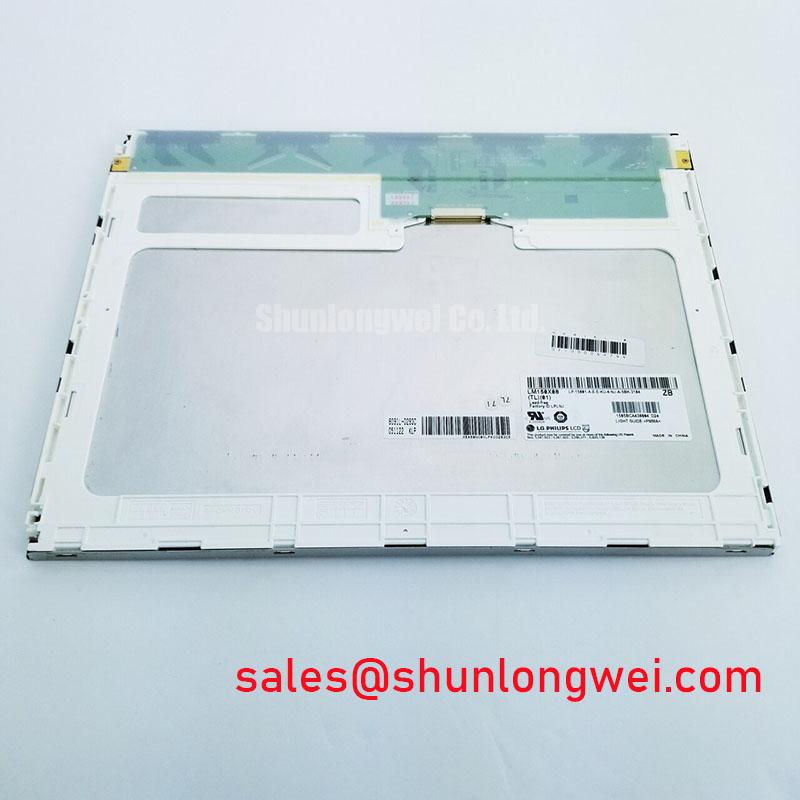
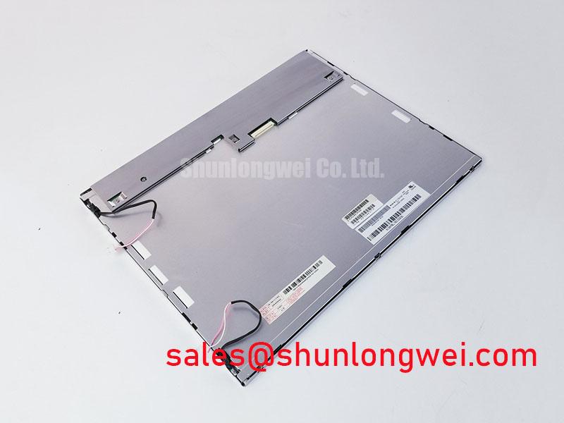
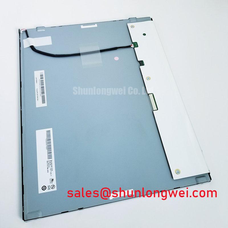
I check the bezel contact pattern with the panel supported in its intended mounting position, before tightening the retaining hardware. For the AUO G150XTN03-8 LCD display, the mechanical comparison should cover the module outline, visible opening, mounting locations, connector clearance and cable exit path. A matching front opening alone does not establish compatibility: rear brackets or a trapped cable can introduce loading that changes the displayed image after assembly.
Design Consideration: compare the enclosure drawing with the panel mounting drawing, including their tolerance limits. The bezel should retain the module through its designated mounting features without pressing on the viewing surface. Where a perimeter gasket is used, its compression should accommodate assembly variation without transferring uneven force into the display. Choose the gasket and retention arrangement through enclosure-level evaluation rather than treating a generic material or compression percentage as an AUO requirement.
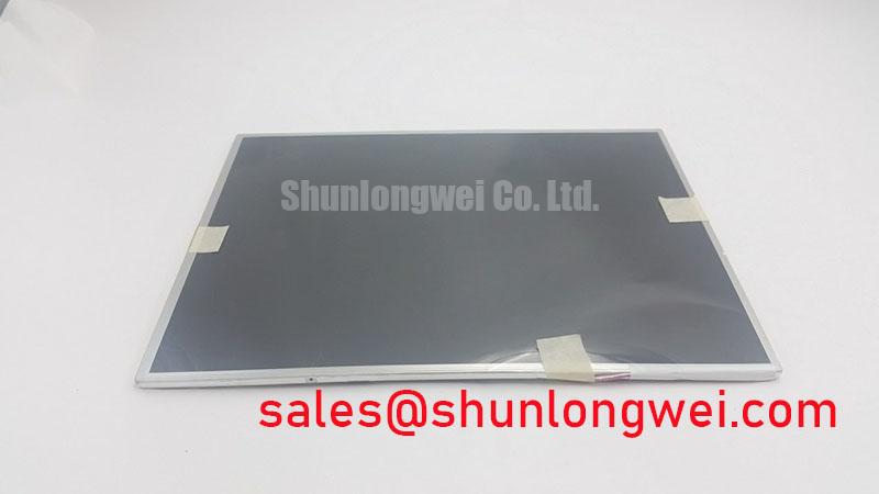
Inspect a uniform dark image before and after fitting the bezel, keeping backlight setting, viewing position and ambient illumination unchanged. New bright patches, shadows or uneven borders after tightening warrant checking bracket alignment, gasket contact and local pressure. These observations can identify an assembly-sensitive condition; they do not establish the composition or condition of an internal optical layer.
Engineering Recommendation: tighten retaining fasteners progressively in an alternating pattern, using the limits specified for the actual mounting hardware and enclosure. A generic screw torque should not become the installation specification for this module. If the image changes during tightening, investigate the load path rather than increasing retention force.
For repair sourcing, record the complete panel designation and compare interface, optical and mechanical requirements independently. The NL8048AC19-14F can be included in a separate display comparison, but should not be treated as a same-size, same-resolution or drop-in replacement without a documented match. For potential railway passenger information systems or cab signalling displays, designers should additionally evaluate viewing geometry and equipment-level qualification; the application name does not establish panel approval.
Constant Luminance Output Control & L70/B50 LED Lumen-Maintenance Reliability Verification
Measure luminance at a fixed viewing position while the assembled display reaches thermal equilibrium, and record the brightness command alongside the result. This separates a commanded brightness change from temperature-dependent drift. For G150XTN03-8 integration, the useful comparison is between the module operating freely on the bench and the same module inside its intended enclosure under equivalent image and control conditions.
Design Consideration: assess the backlight control path as part of the host assembly. In an LED backlight system, regulated current establishes the illumination operating point, while supported dimming controls adjust output. Increasing drive to compensate for declining brightness can also increase thermal loading. Any compensation strategy therefore needs validation against the specified backlight operating limits and the enclosure’s measured thermal behaviour.
Map accessible rear-surface and edge temperatures without obstructing ventilation or changing the mounting arrangement. A concentrated warm region deserves investigation of nearby driver electronics, cable placement and heat transfer into the chassis. An added heat spreader should use an approved external contact path, avoid stressing the module and be evaluated for its effect on temperature distribution. It should not be justified by an assumed internal light-guide material.
L70 describes lumen maintenance at seventy percent of an initial reference, while B50 describes a population percentile associated with the stated criterion. Neither term is interchangeable with fifty-percent brightness retention or mean time between failures. A useful reliability statement must identify the measured quantity, operating conditions and supporting source. No numerical backlight lifetime or population reliability claim is assigned to G150XTN03-8 here.
Engineering Recommendation: characterize brightness-command response across the intended adjustment range rather than assuming that PWM duty cycle produces proportional screen luminance. At lower settings, inspect text readability, visible modulation and transition behaviour. Select the operating dimming conditions from the supported driver requirements and system measurements, including user observation where the display is viewed directly.
Viewing-angle colour changes should also be assessed from the actual operator positions. Brightness adjustment cannot correct every angular contrast or colour shift, and the TFT-LCD classification alone does not establish IPS or MVA behaviour. Use representative text, neutral greys and coloured indicators to evaluate readability before changing host colour processing.
Incoming Benchtop Inspection: COG/TAB Anisotropic Conductive Film (ACF) Integrity
Display full-screen red, green and blue images through a compatible controller, then inspect neutral grey and dark fields for persistent lines, unstable regions and nonuniform illumination. Keep the source configuration and cable arrangement fixed while recording each result. This establishes a reproducible incoming inspection without assigning every visible defect to a driver bond or backlight fault.
Remove power before connecting or disconnecting the display cable. Inspect accessible connector contacts, retention features and cable strain relief without bending the panel or disturbing bonded edges. The COG, TAB and ACF terms describe interconnection technologies encountered in display manufacturing; the section heading is not confirmation of the internal construction of this particular module. Non-destructive bench observations cannot establish microscopic bond integrity.
Design Consideration: if illumination is absent, an oblique external light can help determine whether an image remains visible. A faint image supports investigating the illumination supply and control path, but is not a complete diagnosis. Persistent lines should instead be compared across different patterns, a known-good source and a verified cable arrangement. Avoid pressing the display edge as a diagnostic shortcut.
Confirm interface type, connector pin assignment, signal direction and timing before enabling the source. Where LVDS is specified, align the transmitter’s lane arrangement, colour depth and JEIDA or VESA mapping with the receiver requirements. A physically mating connector does not establish electrical compatibility. TTL signalling requires its own applicable timing and loading checks and should not be treated as an interchangeable differential interface.
Grey-scale errors deserve a source-side check before any intervention around the timing controller. Compare the test image, output format and colour-processing settings, then assess whether the error follows the source or remains with the panel. Gamma-related appearance can arise at several points in the signal chain; changing internal reference circuitry without an approved procedure risks obscuring the original condition.
The physical background of TFT switching is discussed in Amorphous Silicon (a-Si) TFT Technology, without establishing the semiconductor process used in G150XTN03-8. For broader host-interface and enclosure troubleshooting, Industrial Display & HMI Solutions provides complementary engineering context.
Suppressing Acoustic Capacitor Buzz & EMI Emissions across 200 Hz to 1 kHz PWM Frequencies
Correlate audible noise with the brightness command while monitoring the backlight driver supply and control waveform. The frequency band in this heading is an investigation range, not a declared G150XTN03-8 PWM specification. Test only control settings supported by the actual driver, and observe whether noise follows pulse repetition, load transitions or mechanical coupling into the enclosure.
Design Consideration: pulsed loading can excite power-stage components or nearby structures, so the loudest location need not be the electrical source. Compare operation at stable brightness settings and during adjustment, then inspect supply disturbances and driver mounting. Changing PWM frequency alone can move an acoustic symptom without resolving its cause or preserving the intended dimming response.
Identify the backlight architecture from the module and driver documentation before probing it. CCFL ignition behaviour belongs to a different power-conversion system and should not be imported into this product’s operating specification. Likewise, a driver’s dimming ratio does not establish panel brightness linearity or a backlight lifetime guarantee.
💡 Pro Tip: Where LVDS is specified, preserve differential-pair symmetry through the connector transition and verify receiver timing margin with the final cable and brightness-control circuitry operating.
Engineering Recommendation: assess clock stability, data alignment and signal integrity under the intended thermal and loading conditions. Keep illumination switching currents away from sensitive signal-return paths where the layout permits, then verify the result at system level. Resolve acoustic behaviour, image stability and measured emissions as separate acceptance items; component integration alone does not establish equipment EMC compliance.