

Content last revised on October 13, 2026
Shielded FFC/FPC Flat Flexible Cable Grounding across 360-Degree Connector Shells
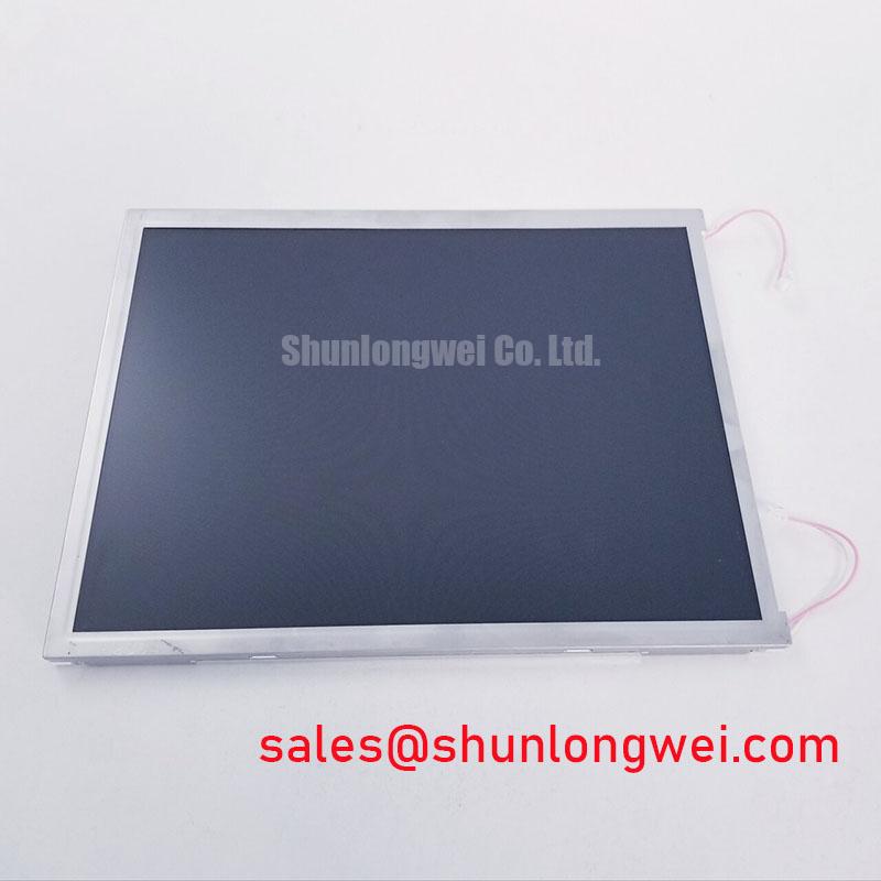
I first separate stationary pixel defects from interference by displaying solid-color fields and checking whether the disturbance changes with nearby drive operation. For a CLAA150XG02Y incoming inspection, record persistent bright or dark points by screen location, then examine horizontal bands and moving noise separately. A repeatable pixel defect and a load-dependent image disturbance require different investigations; neither observation alone identifies the failed component.
Design Consideration: Where the equipment harness includes shielding and conductive connector shells, evaluate shield continuity through the complete cable assembly. Circumferential shield termination can reduce the discontinuity introduced by a long drain-wire connection, but it depends on the connector construction and chassis arrangement. Do not treat a flexible cable as shielded simply because its exposed conductors are covered. Inspect the actual harness, retention hardware, and grounding path.
Compare the display with nearby switching equipment inactive and active while keeping the image pattern unchanged. If the disturbance tracks drive operation, examine cable routing, chassis bonding, and power-supply noise before modifying the panel connection. Common-mode suppression components belong to a system-level investigation: their placement and characteristics should be evaluated against the measured interference without degrading the wanted signal. A quieter screen is useful evidence, not proof of complete equipment EMC compliance.
💡 Bench Tip: With power removed and ESD protection in place, seat the display cable squarely and engage its retention mechanism before restoring power.
Keep brightness drift out of this interference diagnosis. Measure luminance after a consistent warm-up and retain the same brightness command between comparisons. General display operation is described in Thin-Film-Transistor Liquid-Crystal Display technology; the distinction between pixel modulation and illumination helps prevent a dim backlight from being misclassified as a data-link fault.
High-Humidity Storage Margins (60°C / 90% RH) & Delamination Prevention Protocols
Inspect the display edges, connector area, and visible optical surfaces before moving a stored panel into a powered test fixture. The temperature and humidity condition in this heading is an environmental evaluation condition, not an established CLAA150XG02Y storage rating. Qualification conditions must come from the applicable product specification rather than from a generic industrial test profile.
Design Consideration: Allow a cold assembly to equilibrate in a controlled environment before energizing it when condensation is possible. Look for moisture traces, edge lifting, localized haze, and changes in image uniformity without pressing the optical stack. Photograph suspect areas under consistent illumination. Mechanical pressure and contamination can produce similar visible symptoms, so inspection records should distinguish surface marks from effects visible only with the display operating.
At lower temperatures, liquid-crystal switching can slow, making moving edges or gray transitions appear delayed. Compare the same transition pattern at stabilized temperatures while keeping source timing and brightness settings unchanged. This separates temperature-dependent response from an intermittent cable fault. Any proposed heating arrangement requires enclosure-level thermal assessment; it is not a standard accessory or an established requirement for this panel.
For outdoor readability, evaluate the assembled display under representative ambient illumination rather than relying on a dark-room contrast figure. Cover-glass reflections, viewing angle, surface contamination, and enclosure geometry affect what the operator sees. Anti-glare and anti-reflection treatments should be assessed as properties of the actual supplied optical assembly, not assumed features of the module. The Winstar industrial TFT-LCD display resources provide useful context for comparing display technologies, without establishing CPT-specific optical ratings.
Controlled 100-Ohm Differential Impedance Flex Routing to Suppress High-Frequency Jitter
Match the controller pin assignment to the panel connector before investigating image mapping or clock quality. Supply connections, grounds, signal direction, and cable orientation must agree with the exact assembly drawing. The CPT CLAA150XG02Y product page identifies the purchasing model; electrical compatibility requires the corresponding panel specification and equipment schematic.
Design Consideration: A 100 Ω differential impedance is a common LVDS interconnect reference, not a verified routing requirement for this particular module. Apply it only where the documented interface calls for it. Preserve pair coupling and a continuous return path, and evaluate connector transitions and cable bends as part of the complete channel. Differential LVDS guidance should not be applied indiscriminately to a parallel TTL interface.
If the image shows incorrect colors, repeated regions, or a split-screen pattern, compare controller output configuration with the documented pixel format and timing. JEIDA and VESA mapping conventions matter when the identified interface uses those conventions; changing mapping without checking the receiver requirements can obscure the original fault. Check the supply ramp, data validity, and illumination-enable sequence against the specified timing relationship rather than importing a generic startup interval.
Use an appropriate probing arrangement when inspecting differential signals, since probe loading and an unsuitable ground connection can change the waveform being measured. Compare clock stability and data timing at the receiving end under representative cable placement and equipment operation. Interpretation should include the transmitter specification, receiver requirements, and measurement bandwidth.
When comparing NL8048AC19-13, treat it as a separate display candidate, not a drop-in substitute. Compare active area, outline, mounting locations, resolution, interface, illumination connections, and timing individually. For an AGV or forklift telematics display assessment, enclosure vibration, connector retention, and any separate touch assembly also require verification; glove and wet-touch behavior belongs to the touch subsystem, not the LCD designation.
Constant Luminance Output Control & L70/B50 LED Lumen-Maintenance Reliability Verification
Measure full-screen luminance and color uniformity before changing the brightness-control setting. Use repeatable measurement positions, a fixed viewing geometry, and an unchanged test image. Record warm-up behavior separately from stabilized output so an initial brightness change does not become an unsupported aging conclusion.
Design Consideration: L70 describes retention of a specified proportion of initial luminous output, while B50 describes the population fraction associated with the stated maintenance criterion. Neither term means half brightness, and neither establishes a lifetime for the CLAA150XG02Y. LED maintenance terminology also does not establish this module’s illumination architecture. A constant-current driver, where applicable to the documented light source, does not by itself guarantee constant luminance.
Inspect the assembled display for localized heating, blocked ventilation, and mechanical contact that distorts the image. An external heat spreader should be evaluated through enclosure measurements and mounting constraints, not selected from an assumed internal material or an arbitrary rail dimension. Record brightness and color changes alongside temperature so thermal effects are not confused with permanent optical degradation.
For a dim image, compare the commanded brightness, illumination supply behavior, and screen uniformity before assigning a cause. The Ultimate Guide to Industrial TFT LCD Technology provides supporting context for separating illumination, signal, and optical symptoms. Finish the acceptance check with solid-color fields, gray transitions, and a normal equipment screen, documenting persistent defects and connection-sensitive behavior against the agreed inspection criteria.