

Content last revised on October 14, 2026
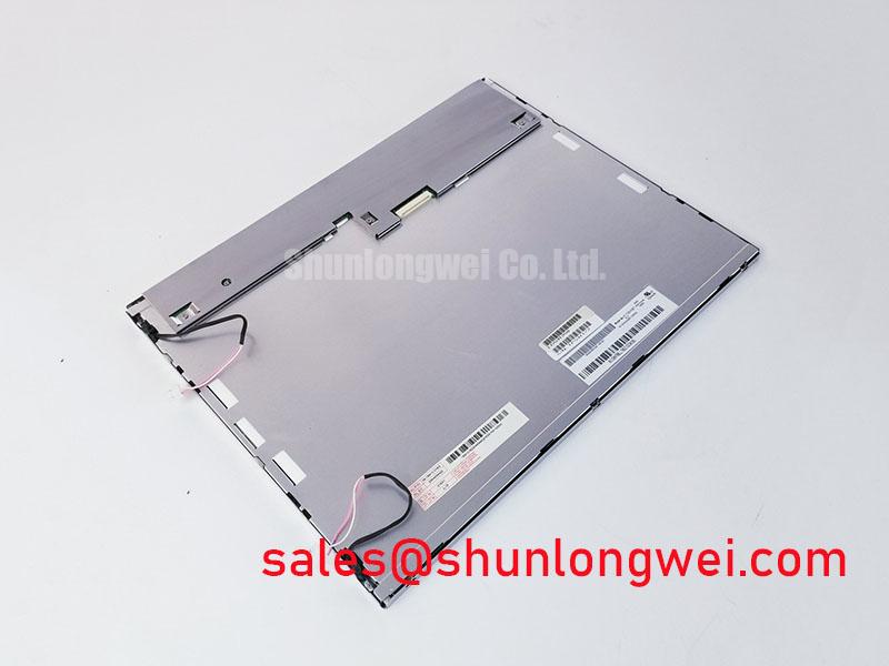
M150XN05-V5 AUO TFT-LCD Panel for Industrial HMI Evaluation
During a field replacement check, isolate power from the precision test instrument, inspect the panel frame and connector area under neutral light, then compare the displayed image against a known-good signal source. The M150XN05-V5 is an AU Optronics (AUO) TFT-LCD Active Matrix Color Display Module. Suitability for an industrial HMI depends on the exact panel specifications and the equipment’s requirements.
This model should be evaluated as a panel-level replacement for equipment such as precision electronic test and measurement instruments, bench analyzers, field analysis meters, and industrial operator interfaces. Compatibility depends on the original system’s mechanical opening, display interface, timing configuration, backlight control, and power architecture. The system integrator should verify these items against the original panel documentation before applying power.
The information presented here does not establish a confirmed supply voltage, active display area, pixel resolution, connector pinout, luminance rating, viewing angle, or backlight lifetime. Those values should remain tied to the matching panel documentation rather than being inferred from the model number. This distinction is important when a repair involves a calibrated instrument in which an apparently functional display may still show timing, grayscale, or optical deviations.
| Product Attribute | Product Information |
|---|---|
| Model | M150XN05-V5 |
| Manufacturer | AU Optronics (AUO) |
| Product category | LCD display panel |
| Display construction | TFT-LCD Active Matrix Color Display Module |
| Application evaluation context | Precision electronic test and measurement instruments |
High-Humidity Storage Evaluation & Delamination Prevention
High-humidity storage evaluation should begin with a controlled visual inspection of the panel perimeter, polarizer surface, connector reinforcement, and bezel edge before the display is energized. Exposure at 60°C and 90% RH is not an established environmental rating for the M150XN05-V5 and should not be used as a test condition without checking the panel’s documented limits and an approved qualification plan. Record the storage history, allow the panel to stabilize gradually without condensation, and inspect for edge haze, localized optical separation, surface bubbles, or changes that appear only after illumination.
Delamination prevention is primarily an enclosure and handling issue. Avoid trapping moisture against the display perimeter, prevent gasket materials from exerting uneven pressure on the active area, and provide a clean transition between the instrument chassis and the panel frame. A gasket can help isolate vibration and contamination, but excessive compression may introduce optical non-uniformity or mechanical stress. The final enclosure should be checked after thermal conditioning rather than approved from a room-temperature fit alone.
At sub-zero temperatures, liquid-crystal viscosity generally rises and gray-to-gray transitions can appear slower. That observation is a physical behavior to evaluate during qualification within the panel’s documented operating limits, not a confirmed response-time specification for this model. Use a controlled gray-step pattern and compare the transition against the same panel at room temperature. Check for trailing, temporary contrast changes, or uneven recovery after the panel returns to normal temperature. If the instrument uses temperature control, assess the display response only after the panel and its surrounding air have reached a stable condition.
The same procedure applies to the perimeter sealing system. Thermal cycling may expose differences in expansion between the chassis, gasket, adhesive interfaces, and display module. Select cycling temperatures from the panel’s documented limits and the approved equipment qualification plan; a range such as −30°C to +85°C must not be assumed suitable for the M150XN05-V5. Inspect the perimeter after cycling for edge lift, haze, visible stress marks, and changes in backlight uniformity.
Backlight lifetime should be assessed through measured luminance rather than assumed from a generic industry figure. A proposed evaluation may track brightness decline under documented backlight drive conditions and use a 50% brightness endpoint as a defined test criterion. A generic 50,000-hour reference does not establish the lifetime of this model without a product-specific source. For repair screening, record initial luminance, temperature, drive condition, and measurement geometry so that later readings remain comparable.
For broader enclosure and HMI reliability planning, engineers can use the Industrial Display & HMI Solutions engineering reference as a related design resource. The external AUO website is also a useful manufacturer-level reference when reviewing display families and optical integration considerations.
Suppressing Pixel Jitter & Horizontal White Lines Induced by Adjacent 400V Motor Drives
When a precision instrument operates beside a 400V variable-frequency motor drive, begin the display investigation with cable routing and reference-plane continuity rather than replacing the panel immediately. Pixel jitter and horizontal white bands can arise from common-mode coupling, connector contact variation, signal-return disruption, or timing sensitivity in the host electronics. The display module itself should be evaluated together with the cable, source board, chassis, and drive installation.
A shielded FFC or LVDS cable should follow a controlled route away from high-current switching conductors. If a 360-degree shield termination is used in the system, confirm that the termination is mechanically continuous and connected to the intended chassis reference. Do not assume that attaching a shield at an arbitrary point will improve performance; an unintended return path can transfer switching energy into the display reference. The correct arrangement is system-dependent and should be verified with the instrument operating in its highest-noise condition.
Common-mode ferrite components may be considered during EMC troubleshooting, but they are not established accessories or internal features of the M150XN05-V5. Their effect depends on cable construction, signal frequency, common-mode impedance, grounding, and the placement of the component. Compare the display waveform and image stability before and after any change, while ensuring that the added component does not degrade the intended differential signal.
Horizontal noise bands should be correlated with the motor-drive switching state, display refresh activity, and cable movement. A stable test pattern makes intermittent artifacts easier to observe than a changing video image. If the artifact follows the drive’s acceleration or regenerative events, capture the display clock and data reference relative to the system ground with suitable probing practice. If the artifact remains when the drive is disabled, inspect connector seating, cable alignment, source-board timing, and panel configuration instead of assigning a single cause.
Cold operation can increase liquid-crystal response time and make motion artifacts more visible. If the instrument includes a heater or controlled warm-up sequence, treat it as a system feature that requires validation. Compare gray-step behavior before and after stabilization, then check whether the apparent white line is an optical response effect or an electrical disturbance that remains synchronized with the data stream.
💡 Bench Tip: Protect the panel and cable from ESD, and insert the FFC fully parallel to the connector before closing its lock; an angled insertion can create intermittent image faults that resemble signal interference.
Display Interface Synchronization & Logic Power Rail Verification
Interface verification must start with the original instrument schematic or panel documentation because the information presented here does not confirm the M150XN05-V5 pin assignment, logic voltage, timing values, or data mapping. Do not select between possible supply rails or assume a TTL or LVDS arrangement from the model number alone. Match the replacement panel’s documented interface to the host board before energizing the module.
For a documented TTL 24-bit RGB connection, inspect the red, green, and blue data groups together with pixel clock, synchronization signals, enable control, and their return references. Incorrect bit assignments or timing can produce abnormal colors or grayscale while the panel still illuminates. For an LVDS connection, also confirm the applicable JEIDA or VESA mapping. The mapping must be confirmed at the transmitter, cable, and receiver rather than judged from connector position alone.
Power sequencing is equally important. The host system should control the logic rail, display enable signals, and backlight command according to the timing relationship specified for the actual panel variant. During bring-up, capture the rail and control signals together and compare their rise, settling, and shutdown behavior with the approved panel documentation.
For high-speed routing, maintain a continuous reference plane and avoid unnecessary stubs at the connector. For differential links, keep paired conductors geometrically consistent. A nominal 100 Ω differential characteristic impedance is a common design target for LVDS display links, but the relevant panel and transmitter documentation must determine the actual routing requirements; it is not a TTL RGB bus requirement. Clock jitter and data hold margin should be checked at the receiving interface across the intended temperature range, especially when a long cable or an intermediate adapter has been added.
T-CON timing, grayscale voltage generation, and gamma correction are part of the complete display system and cannot be inferred from the product category alone. When a replacement produces correct geometry but abnormal gray steps, inspect the source timing, panel configuration, gamma reference behavior, and video test pattern. A full-white image can conceal grayscale errors, so use black, white, intermediate gray, color bars, and moving transitions during incoming inspection.
For an industrial HMI or test instrument, document the connector orientation, cable length, signal mapping, power-on sequence, and image test results as one replacement record. This is more useful than recording only whether the backlight turns on, because a panel can pass a basic illumination check while failing synchronization or tonal uniformity requirements.
Flush-Mount Open-Frame Bezel Integration & Perimeter Gasket Shock Isolation
Flush mounting should be qualified by checking the chassis opening, bezel contact points, gasket compression pattern, and connector clearance with the panel unpowered. A general form-factor description does not provide a confirmed outer bezel envelope or mounting-hole drawing for this model, so the instrument chassis must be compared with the applicable mechanical documentation before machining or fastening.
Use a flat reference fixture to identify any high spots around the opening. A localized contact point can transfer enclosure distortion into the display and create dark-field mura, brightness variation, or pressure-related optical marks. The gasket should support the perimeter without touching active viewing regions or forcing the panel against an uneven frame. After assembly, inspect the image at black, white, and mid-gray levels because dark-field testing often reveals mechanical non-uniformity that is not obvious on a bright screen.
Cross-pattern fastening can help distribute frame loading, but the correct fastener torque is determined by the chassis, fastener size, gasket material, and panel drawing. Use the documented assembly torque rather than a generic starting value. Apply the specified torque progressively and confirm that the image does not change as each fastener is tightened.
Shock isolation should prevent the enclosure from transmitting concentrated force into the display perimeter. It should not allow the panel to move enough to load the FFC, connector latch, or backlight wiring during transport. Test the completed assembly in its final orientation, then repeat the image inspection after vibration or handling simulation. Look for intermittent lines, edge darkening, new bright points, or a change in color uniformity rather than relying only on a continuity check.
Viewing-angle and color assessment should be performed from the actual operator position. Wide-angle optical behavior, IPS or MVA characteristics, and off-axis color compensation must be confirmed from the exact panel documentation; they should not be assigned to the M150XN05-V5 solely from the industrial LCD category. Use a fixed test image and consistent observer or camera geometry when comparing the replacement with the removed display.
Backlight thermal distribution also deserves attention in a flush enclosure. Keep the display perimeter, driver region, and adjacent instrument heat sources within the system’s validated thermal conditions. If a local hot area appears, first map the enclosure temperature and illumination uniformity, then review airflow, spacing, and driver operation. Avoid adding pressure, insulation, or adhesive near the panel until the mechanical and optical consequences have been checked.
For service procurement, provide the supplier with the exact model marking, the original equipment application, connector photographs, mechanical drawing, and interface documentation. That information allows the M150XN05-V5 to be evaluated as a panel replacement for the intended precision measurement instrument rather than as a generic display with assumed electrical compatibility.