

Content last revised on October 17, 2026
Direct Sunlight High-Ambient Readability without Active Backlight Illumination
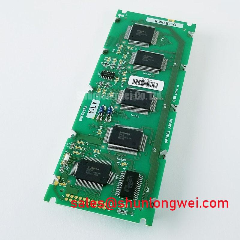
When a factory machine-tool terminal shows missing rows, weak contrast, or an intermittent image, isolate power before removing the bezel and inspect the panel edge, connector seating, and cable locking condition. The DMF5005NY-LY is an OPTREX monochrome passive-matrix LCD module. The system integrator should verify the required supply voltage and interface timing from the original panel documentation.
This display format is commonly evaluated for factory automation machine tools, operator terminals, and industrial control panels where monochrome readability, mechanical serviceability, and compatibility with an existing display controller matter more than a modern TFT replacement architecture. When comparing physical fit and signal behavior, engineers can also review the LM8V311 as a separate display reference rather than assuming electrical interchangeability.
Start a daylight readability check with the terminal operating under its normal enclosure conditions, then compare characters in direct ambient light against a shaded reference area. An FSTN or STN monochrome panel with a reflective or transflective optical stack can preserve useful reflective contrast when the polarizer, front window, and bezel are clean and evenly supported. The assessment should focus on actual character visibility rather than brightness alone.
Legacy industrial displays may develop optical degradation after extended exposure to ultraviolet radiation, heat, cleaning chemicals, or repeated temperature cycling. Iodine-based polarizer aging can reduce contrast, while adhesive bubbling or local separation can create cloudy zones that become more obvious under sunlight. These effects should be mapped across the active viewing area before deciding whether the panel, front filter, or mechanical bezel is responsible.
For installations that previously used a cold-cathode fluorescent lamp, the lighting assembly must be treated as a separate high-voltage subsystem. A cold-strike pulse in the 1200–1600 Vrms range and sustained operation in the 300–600 Vrms range are engineering reference values for CCFL circuit evaluation, not confirmed DMF5005NY-LY panel ratings. Designers should establish creepage, clearance, transformer insulation, and corona control from the actual inverter construction and applicable safety requirements. The display panel itself should not be presented as independently certified for system-level EMC or insulation performance.
When sunlight is part of the operating environment, inspect the front surface for residue and micro-scratches before judging the polarizer. General polarizer behavior can be reviewed through this polarizer technology reference; it does not establish the polarizer construction used in this module. The enclosure designer should also control reflections from protective glass, painted bezels, and nearby indicator lamps.
Cleaning Zebra Rubber Strips and PCB Gold Contact Pads
Missing rows or columns warrant inspection of accessible connections first. If the assembly uses a serviceable elastomeric zebra strip, follow its disassembly instructions, release the bezel evenly, lift the panel without twisting its edge, and inspect the strip for displacement, compression marks, dust, or contamination on the mating PCB pads. Anhydrous IPA may be used sparingly on suitable gold contact surfaces with a lint-free swab, provided the cleaning method is compatible with the panel materials and the assembly is fully dry before re-energization.
A zebra strip depends on alignment and distributed pressure rather than a conventional soldered connection. A bezel that clamps unevenly can produce localized open segments, while vibration or repeated service access can shift the strip by a small amount. The required compression must follow the connector and assembly documentation, taking account of the original frame and gasket geometry.
Do not scrape the gold pads, flood the strip with solvent, or force the glass edge against the frame. After cleaning, place the strip in its original orientation and tighten the bezel progressively so that pressure is applied evenly across the display perimeter. A missing image band that changes when the frame is gently supported may indicate contact displacement, but the same symptom can also come from controller timing, cable damage, or a board-level fault.
The controller’s parallel interface should be checked as a complete signal path. Four-bit or eight-bit data arrangements can use control signals such as CP, LP, and FLM, but the supported bus width and exact pin assignment must follow the original panel and controller documentation. Clock jitter, ground bounce, and poor cable retention can disturb data capture even when the panel itself is optically intact. For power sequencing, follow the documented order for the logic supply, interface signals, and LCD bias supply; supply names and sequencing requirements must be confirmed for the actual assembly.
⚠️ Maintenance Note: Inspect the bezel seal, ventilation path, and connector seating during scheduled service because dust ingress and uneven compression can gradually change image quality.
Digital Parallel Bus Timing: Frame Sync, Line Pulse and Shift Clock
Use an oscilloscope at the controller-side connector to compare frame sync, line pulse, and shift-clock activity with a known-good operating cycle. Where these signal names are used, FLM marks the first line of a frame, LP controls line-data latching, and CP shifts pixel data; their relationship must remain consistent with the panel’s documented interface and bus width. A stable image with intermittent bands should be investigated by correlating the visible defect with the timing sequence rather than assigning a single cause.
Signal integrity depends on cable length, return-path quality, connector locking, edge rate, and the electrical loading of the receiving panel. Keep the parallel bus routing orderly, avoid unnecessary stubs, and confirm that the cable shield and signal return arrangement match the equipment’s original design. When a replacement controller is involved, compare idle levels, pulse polarity, frame repetition, and line ordering before changing software timing.
Power-up behavior deserves equal attention. Applying LCD bias before the required logic and drive signals are established can create unwanted DC stress across the liquid crystal, while an incomplete reset may leave the controller in an indeterminate state. Designers should verify the actual sequencing delay and polarity from the panel and controller documentation and monitor the supply rails during startup. A panel that develops persistent shading after an incorrect sequence may require optical and electrical inspection together.
Cold environments can slow liquid-crystal response and make apparent contrast or ghosting more noticeable during startup. This temperature-dependent response should be separated from a defective bus waveform by observing the display after thermal stabilization. Mechanical expansion between the glass, bezel, PCB, and flexible cable can also alter contact pressure. Any enclosure redesign should allow stress to distribute across the frame rather than concentrate at the connector edge.
For machine-tool terminals communicating with a PLC, the display should be considered part of the operator interface while any Modbus link remains a separate control-layer concern. A useful protocol reference is the Modbus overview. It can help separate communication faults from panel timing faults during HMI service work.
CCFL Ballast Capacitor Selection and Tube Operating Current Stabilization
When the installed terminal uses a CCFL backlight assembly, begin with the inverter and lamp wiring rather than applying high voltage directly to the panel. The commonly cited 5.0 mA ± 0.5 mA tube-current target is an engineering reference for a compatible CCFL ballast design, not an official DMF5005NY-LY rating. The correct operating current, ignition behavior, and lamp load must be taken from the original backlight assembly and inverter documentation.
A ballast capacitor that is unsuitable for the transformer and lamp can increase strike stress, create unstable brightness, or encourage corona at sharp conductors. The earlier 1200–1600 Vrms ignition reference should therefore be treated as a high-voltage design consideration only. The system engineer must verify insulation spacing, transformer winding construction, connector voltage rating, and discharge behavior during service testing.
Keep the high-voltage path physically separated from logic wiring and reflective metalwork, and inspect transformer potting, wire routing, and connector strain relief for evidence of tracking or mechanical abrasion. The LM320194 may be reviewed as a separate display reference, but compatibility with a DMF5005NY-LY assembly must not be assumed.
For long-term HMI service, avoid leaving a static alarm or menu screen continuously active when the controller supports screen rotation or periodic blanking without compromising alarm visibility. PWM dimming, if present in the equipment, should be evaluated at the system level for visible modulation and driver compatibility rather than assigned as a panel specification. Flexible cable bends should remain gradual, and the connector lock should be engaged only after the cable is fully aligned. Broader background on industrial LCD selection, optical aging, and interface integration is available in The Ultimate Guide to Industrial TFT LCD Technology, although TFT interface details should not be applied directly to this passive-matrix module.