

Content last revised on October 12, 2026
Suppressing Ghosting and Crosstalk via Precision Multi-Level Bias Voltage Dividers
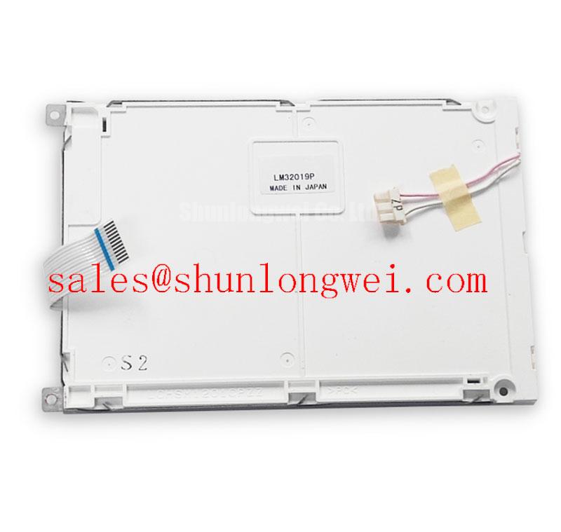
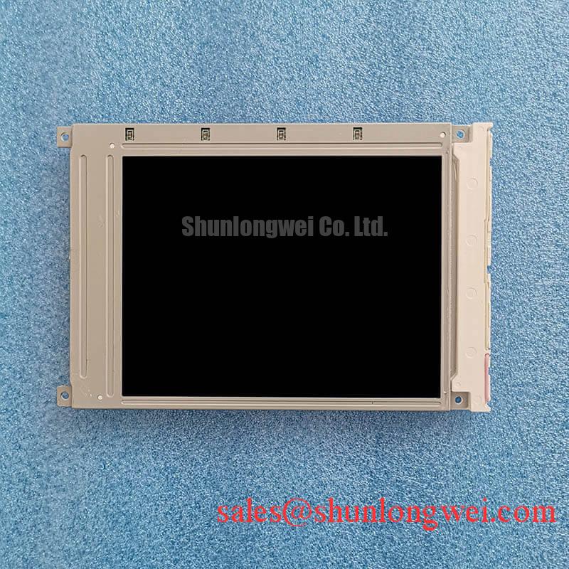
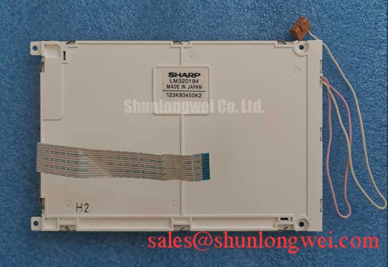
When a replacement panel shows faded contrast, ghost characters, or unstable segments, I first separate panel behavior from the host controller by comparing the display timing and bias rails with a known-good assembly. The Sharp LM320194 is identified as an FSTN/STN monochrome passive matrix LCD panel in a standard form factor. Its published product classification does not establish a universal negative bias voltage, ripple limit, or temperature compensation network, so those values must remain system-level design parameters rather than being assigned to the panel as factory ratings.
A passive matrix display depends on controlled voltage levels and correctly timed row and column addressing. A bias divider that drifts with temperature can alter perceived contrast without creating an obvious open circuit. For a factory automation machine tool or HMI operator terminal, technicians should inspect the negative bias rail at the panel connector while the display is operating across the expected cabinet temperature range. Ripple, ground reference movement, and regulator recovery during display updates are more useful observations than a single static voltage reading.
Thermistor compensation may be present in the original host circuit, but it should not be assumed to be integrated into LM320194. Compare the replacement assembly with the original wiring, controller board, and contrast adjustment network. If the image changes as the cabinet warms, record the rail behavior and display response together. This helps distinguish temperature dependent liquid crystal contrast variation from connector pressure or timing faults.
The elastomeric connector interface also deserves careful attention. Zebra strip compression must be even across the active width; excessive local pressure can create intermittent rows, while insufficient pressure can produce missing columns or contrast bands. Cleaning exposed gold contacts with anhydrous IPA is a general maintenance practice, not an LM320194 manufacturer specification. Allow the interface to dry completely before reassembly and avoid scraping the contact surface.
For a same-size or same-resolution evaluation, engineers may compare the host mechanical drawing and interface arrangement with LM14X79. This is a reference point for compatibility assessment, not a substitute recommendation. The controller timing, connector geometry, optical stack, and mounting bezel still require direct comparison.
Elastomeric Zebra Strip Connector Compression and Heat Seal Interconnect Integrity
Missing rows and columns should be approached as an interface alignment problem before changing the display controller. Remove power, release the bezel evenly, and inspect whether the zebra strip remains centered over the glass contact pattern. Vibration, uneven screw loading, oxidation, and repeated thermal expansion can shift the contact path enough to create image defects that appear intermittent during machine operation.
The mechanical frame should distribute pressure across the display edge rather than concentrating force at isolated screw points. This is a general design consideration for passive matrix LCD assemblies; the product information supplied for LM320194 does not define a factory bezel torque or a certified compression window. When rebuilding the assembly, use the original frame geometry and verify the result at cold start, normal operating temperature, and after controlled vibration exposure appropriate to the equipment.
Heat seal connections and elastomeric interfaces should not be treated as interchangeable construction methods. A replacement panel must match the host connection style, contact pitch, viewing orientation, and active area. A panel that fits the cutout can still fail electrically if the driver board expects a different row or column arrangement.
Some legacy terminals use a cold cathode fluorescent lamp system, while other assemblies use a different illumination arrangement. The available LM320194 classification confirms an FSTN/STN monochrome passive matrix LCD panel, but it does not confirm a CCFL lamp, ignition transformer, ballast, or lamp current rating. Any high voltage lighting circuit must therefore be evaluated from the original terminal documentation and measured with probes rated for the circuit.
⚠️ Maintenance Note: Inspect the bezel seal, display support points, and cabinet cooling path during scheduled service so dust ingress and thermal stress do not compromise the connector interface.
For power topology work around a legacy display assembly, the related LMG7401PLFC may be reviewed as a separate auxiliary or front-end device reference. Its presence in a system must not be inferred from the LM320194 panel classification.
Direct Sunlight High-Ambient Readability without Active Backlight Illumination
Readability in direct sunlight depends on the complete optical and mechanical assembly, not the LCD panel designation alone. FSTN and STN monochrome panels are often evaluated in equipment where ambient reflection is significant, but the exact polarizer, reflector, adhesive, and illumination construction for LM320194 should be confirmed from the original assembly documentation.
When an older operator terminal becomes difficult to read outdoors or near high intensity plant lighting, compare the display under controlled viewing angles and identical contrast settings. Look for localized bubbles, haze, delamination, uneven coloration, or a surface that changes appearance after warm-up. These observations can indicate aging in the optical stack or bonding materials, but they do not identify a single failed layer without inspection of the complete panel.
Sunlight exposure also increases the importance of bezel sealing and enclosure design. Designers should evaluate ultraviolet exposure, condensation, pressure on the glass, and the temperature gradient between the front surface and the rear electronics. A protective window must not introduce excessive reflections or press against the active display area. The panel supplier classification alone does not establish an outdoor rating or a guaranteed sunlight lifetime.
The host controller must also be checked for correct parallel bus timing. Signals commonly labelled CP, LP, or FLM belong to the system interface and should be compared against the original controller waveform. Clock edge distortion, ground bounce, or an incorrect power sequence can produce unstable characters even when the replacement glass is mechanically sound. Designers should verify the required power-up sequence for the original controller and panel rather than assume that the logic supply must always precede the negative bias rail, then validate the sequence with the display connected.
Sharp’s industrial display resources at Sharp Display Solutions Official Portal and Sharp Devices Europe Industrial Display Solutions provide useful manufacturer context for display integration. They should be used alongside the exact host equipment documentation when assessing optical performance, interface timing, and environmental suitability.
Cold Cathode Fluorescent Lamp High Voltage Strike Waveform and Open Lamp Trip Threshold Tuning
High voltage lamp behavior must be treated as a property of the complete backlight assembly, not as an automatic characteristic of the Sharp LM320194 panel. The available product classification identifies an FSTN/STN monochrome passive matrix LCD panel and does not assign a CCFL ignition voltage, sustained lamp voltage, lamp current, transformer design, or open lamp trip threshold.
If the original HMI uses a CCFL inverter, inspect the transformer insulation, cable routing, connector condition, and ballast behavior before connecting a replacement panel assembly. Strike and run waveforms should be captured only with measurement equipment and probes suitable for the circuit. Abnormal corona, repeated restart attempts, or a protection trip may originate in the inverter, lamp, cable, connector, or control feedback path rather than in the LCD glass.
Maintain physical separation between high voltage lighting conductors and low voltage display logic. Creepage and clearance should be selected according to the equipment insulation system, pollution environment, working voltage, and applicable safety standard. These are system design requirements, not confirmed LM320194 specifications. The inverter protection threshold should likewise be set from the lamp and transformer design documentation, with the open load response verified under controlled service conditions.
Parallel display timing remains relevant during backlight troubleshooting. Observe CP, LP, and FLM at the panel interface while the illumination circuit is enabled and disabled. A shared ground disturbance or supply transient can make a lighting fault appear to be a display data fault. Check the logic rail, bias rail, and inverter control signal as separate paths, then compare their timing against the original working assembly.
For broader cabinet sealing, thermal management, and HMI integration considerations, consult Industrial Display & HMI Solutions. LM320194 remains suitable for evaluation only when its mechanical format, passive matrix interface, optical requirements, and host electrical conditions match the equipment being serviced.