

Content last revised on September 13, 2026
Backlight Inverter Ignition and Startup Debugging
Before connecting the LMG7401PLFC to a replacement controller or inverter, identify whether the original assembly uses an external CCFL inverter, an integrated LED backlight driver, or another manufacturer specific arrangement. The supplied factory data identifies the product as a TFT LCD display module, but it does not confirm a CCFL lamp configuration, dual channel inverter input, cold ignition voltage, operating lamp voltage, LED current, PWM dimming ratio, or backlight connector assignment. These details are system interface requirements and must be taken from the original panel documentation.
For a field replacement, begin with a visual inspection of the display cable, backlight connector, locking tabs, and exposed flex areas. Check for bent contacts, contamination, cracked solder joints, or signs that the cable has been inserted at an angle. With power removed, compare the replacement connector arrangement with the known good unit. A resistance reading across a backlight connector can be misleading because the connected driver topology affects the measured result; it should not be used alone to approve or reject the panel.
When the equipment uses a high voltage fluorescent backlight, the inverter should be tested separately with the correct probe and safety procedure. A failed ignition attempt can involve the inverter, lamp circuit, protection feedback, wiring, or the panel itself. Engineers should observe the enable signal, brightness control signal, inverter output behavior, and protection shutdown with an oscilloscope suitable for the circuit. Do not substitute an LED constant current driver for a fluorescent inverter unless the complete display assembly and its electrical requirements have been confirmed.
If the original system uses LED backlighting, verify the required LED forward voltage range, regulated current, enable polarity, and dimming method from the source documentation. A panel may require a specific PWM or analog control scheme, and a visually similar connector does not establish electrical compatibility. The system integrator should verify the required supply voltage from the original panel documentation before connecting the unit.
Acoustic noise during startup or brightness changes should be investigated at the inverter, mounting frame, and cable routing points rather than assigned automatically to the LCD module. A controlled comparison with the known good display can help separate a backlight drive issue from a mechanical resonance. Optical contrast under direct sunlight, anti glare performance, and any claimed half life or reliability figure also require a manufacturer data sheet or controlled system test. The supplied product information does not establish a contrast ratio, anti glare treatment, backlight half life, or MTBF value for this model.
Chassis Fastener Torque Sizing and Optical Mura Inspection
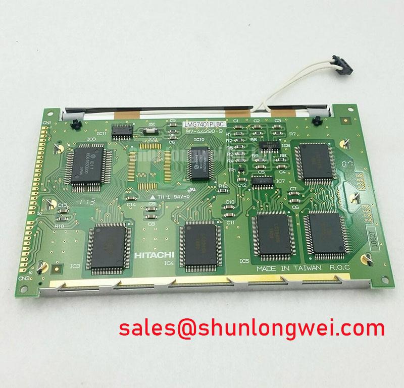
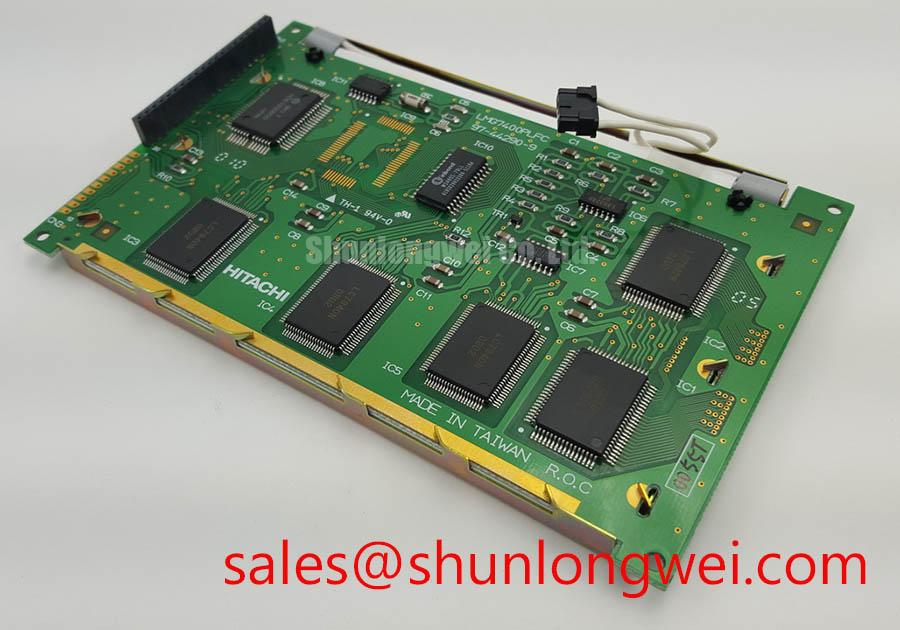
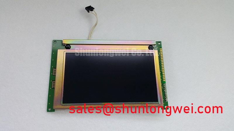
Mechanical compatibility should be checked before the first powered test. Compare the panel outline, visible area, bezel opening, mounting hole pattern, connector clearance, and cable bend path with the equipment chassis. The available factory record confirms the package as a TFT LCD Display Module but does not state the external dimensions, mounting hole tolerances, screw size, or allowable fastening torque. These measurements should therefore be taken from the original assembly drawing or verified directly against the replacement unit.
When an M3 fastener is used by the equipment manufacturer, the permitted torque remains a chassis and assembly design requirement unless the panel manufacturer provides a specific value. A general industry mounting practice may be used only as a starting point during bench fitting, followed by inspection for frame distortion, glass stress, and uneven bezel contact. Tightening should be gradual and distributed across the available mounting points. A cross pattern can help distribute mechanical loading, but the final procedure must follow the equipment manufacturer’s service instructions.
Dark-field inspection is useful after mechanical installation. Display a uniform black, gray, and white test image and examine the screen from the intended operating position. Local brightness variation may result from frame pressure, cable interference, uneven support, optical stack differences, or the display signal path. It should not be treated as proof of a single internal defect without comparison against a known good assembly.
💡 Pro Tip: Disconnect power before inserting or removing the display cable, and confirm that the connector locking mechanism is fully seated before applying power.
Signal integrity also depends on the controller and harness. If the interface is LVDS, verify the actual pair assignment, channel order, clock polarity, color mapping, and JEIDA or VESA format from the original documentation. Do not assume that a compatible looking cable uses the same mapping. A panel that powers the backlight but displays a white screen, scrambled image, reversed colors, or intermittent lines may require investigation of power sequencing, panel enable timing, differential pair routing, or data format.
For a high electromagnetic interference installation, the design consideration is to keep each differential pair routed as a controlled, balanced path with a continuous reference plane and minimal unnecessary discontinuity. The system designer should determine the target impedance, pair spacing, allowable skew, connector selection, and shielding method from the controller interface requirements and then validate the result with the installed harness. An oscilloscope comparison with the known good signal path can help identify signal quality problems without assigning a fixed diagnostic threshold to the LMG7401PLFC.
For engineers comparing a possible same size or same resolution replacement, the TX23D11VM2BAA may be reviewed as a separate reference product. It should not be treated as a direct substitute until dimensions, resolution, connector pinout, interface timing, mounting arrangement, and backlight requirements have been matched.
Backlight Luminance Control and Lifetime Verification
Backlight performance must be evaluated as part of the complete display system. The factory information supplied for the LMG7401PLFC does not specify LED current, luminous output, uniformity, thermal resistance, L70 or B50 life data, or an aluminum heat spreader arrangement. Consequently, these values cannot be presented as official characteristics of this model. They should be obtained from the applicable panel data sheet or measured on the assembled equipment under its actual enclosure and ambient conditions.
During replacement testing, allow the display to reach a stable operating condition and compare luminance at several screen locations using the same image, controller settings, and measurement geometry. Record the result together with enclosure temperature, backlight command, supply condition, and airflow state. This is an engineering verification procedure, not a manufacturer life prediction. Long term degradation depends on LED drive conditions, thermal transfer, ambient temperature, operating duty, optical materials, and the surrounding mechanical design.
Where the display is installed in a sealed operator console, designers should examine the heat path from the backlight and controller toward the chassis. The useful design principle is to avoid trapping heat near a narrow display edge or connector area. Any heat spreader, conductive frame, pad, or bracket must be selected according to the actual mechanical construction and electrical insulation requirements. The presence, material, and thickness of such parts must not be assumed from the LMG7401PLFC model number.
Brightness control should be checked at the controller output and at the backlight driver input. If a PWM signal is used, verify its logic level, polarity, frequency, duty response, and startup behavior from the original system specification. If analog control is used, verify its permitted range and reference ground. The supplied product record does not confirm a particular dimming method, so a constant current LED driver should not be connected without confirming the panel’s backlight interface.
Power sequencing deserves the same attention as luminance. The integrator should establish the order and timing relationship between logic supply, reset, display enable, video clock, data lanes, and backlight enable from the original controller documentation. White screen behavior, residual images during shutdown, or failure to restart can involve timing conflicts between the controller and the backlight circuit. A practical bench test is to capture the relevant supply and control waveforms during startup, normal brightness changes, and power removal, then compare them with a known good assembly.
For a potential telematics display in heavy earthmoving equipment, the enclosure should also be assessed for vibration transfer, dust sealing, condensation, cable strain, and sunlight exposure. These are application level design considerations, not confirmed environmental ratings for this LCD module. The appropriate validation method is to test the complete display, bezel, cable, controller, and enclosure as an assembly. Engineers reviewing sealing and harsh environment integration may also consult Industrial Display and HMI Solutions for broader system planning context.
Viewing-Cone Assessment for Multi-Angle Consoles
The available product record does not identify the LMG7401PLFC liquid crystal mode as TN, IPS, Super IPS, or MVA. It also does not publish a viewing angle, contrast ratio, grayscale response, color gamut, surface treatment, or sunlight readability rating. These optical parameters must be verified from the original KOE / Hitachi documentation or measured on the actual unit. A wide viewing angle should never be inferred solely from the industrial LCD category.
For a multi angle operator console, assess the screen from the left, right, upper, and lower working positions while displaying neutral gray steps, saturated colors, fine text, and a uniform white field. Look for grayscale inversion, color shift, loss of shadow detail, reflections, and localized brightness change. The display should be evaluated at the viewing positions used by the equipment operator, not only from a perpendicular laboratory position.
Surface treatment is equally important. An anti glare finish may reduce mirror reflections but can also affect perceived sharpness, black level, or fine character definition depending on the optical stack and ambient illumination. The supplied information does not confirm an anti glare coating or etching process for this model. When replacing a panel, compare the surface appearance and readability with the original unit under the same cabin lighting and external daylight conditions.
Timing controller configuration can affect perceived grayscale quality even when the LCD glass is mechanically compatible. Confirm the resolution, pixel clock, horizontal and vertical timing, data mapping, color depth, and power on sequence before judging optical behavior. If the replacement requires a different T CON configuration or gamma arrangement, the controller manufacturer’s documentation should define the valid settings. Do not apply generic gamma voltage values or timing presets without evidence that they belong to this panel.
For a vibration exposed display, route the cable so that the connector is not carrying mechanical load, support the harness near the chassis entry, and maintain clearance from sharp edges. The final bracket and gasket arrangement should be checked for compression, movement, and condensation risk during equipment validation. Where the LMG7401PLFC is considered for a mining shovel or earthmoving equipment telematics display, compatibility remains conditional on the original electrical interface, mounting envelope, optical requirements, and environmental validation.