

Content last revised on October 15, 2026
HV Lead Wire Creepage Insulation and Secondary Transformer Corona Discharge Screening
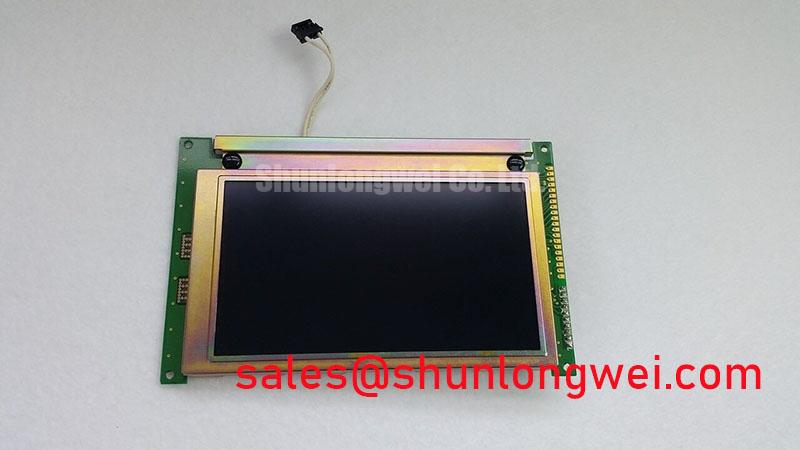
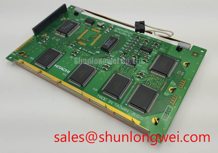
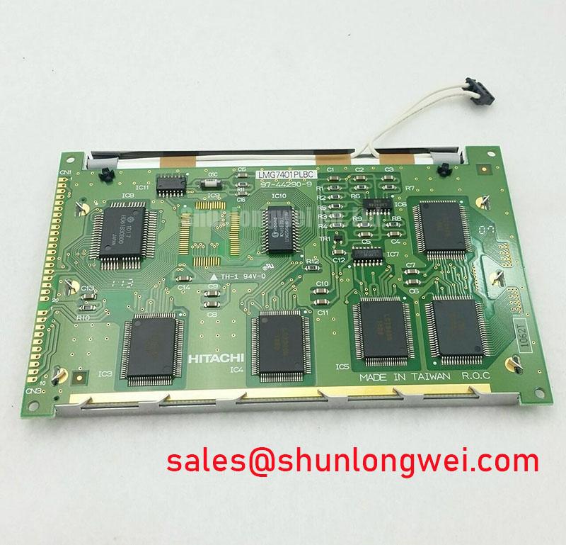
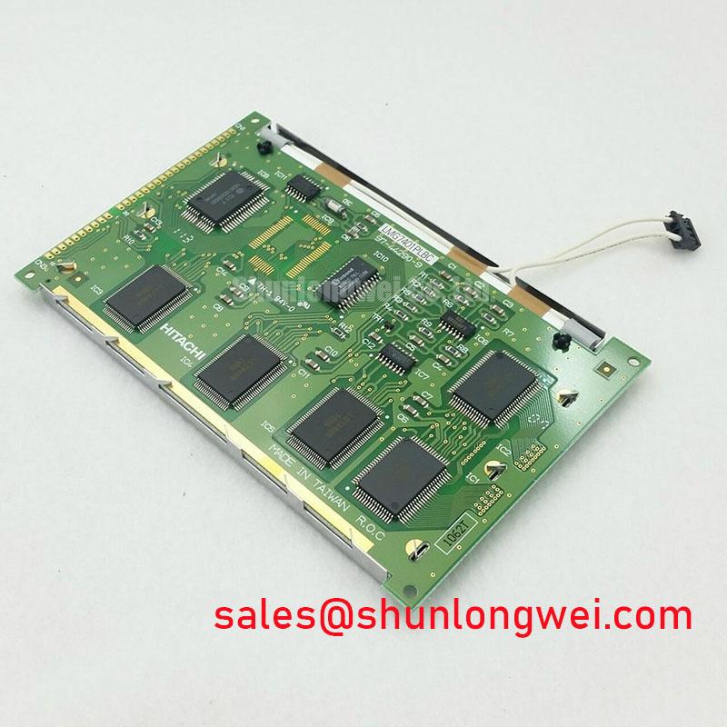
At the bench, isolate the display panel from the instrument’s backlight and high voltage wiring before checking a dark screen, intermittent illumination, or visible corona marks around the secondary transformer. The LMG7401PLBC is identified as a KOE / Hitachi FSTN / STN monochrome passive matrix LCD panel; the available product definition does not assign a high voltage rating, tube current rating, or backlight assembly rating to the panel itself.
For a precision electronic test and measurement instrument, inspect the complete illumination circuit as a system. Look for carbon tracking, softened insulation, discolored transformer resin, loose lamp wiring, and contamination near the high voltage lead path. A cold strike can create a transient stress event before the lamp reaches its sustained operating condition, so the enclosure, wiring route, transformer insulation, and ballast control must be assessed together.
As a Design Consideration, legacy CCFL circuits are often evaluated around a 1200 V to 1600 V RMS ignition pulse and a 300 V to 600 V RMS sustained condition, with tube current regulation commonly assessed near 5.0 mA with a 0.5 mA tolerance. These values describe a possible system backlight architecture, not confirmed ratings for the LMG7401PLBC. The integrator should verify the original instrument schematic and the installed backlight assembly before applying any replacement drive circuit.
The FSTN/STN optical stack also deserves a visual comparison with a known working panel. Iodine polarizer aging can reduce contrast or create uneven dark areas, while thermal exposure may change the apparent response of the liquid crystal layer. In low temperature service, increased viscosity can slow character transitions without proving that the panel has an electrical fault. Compare the display after the instrument has reached its normal operating temperature and examine the reflective background under the same ambient lighting.
Field Alert: Disconnect power and allow the backlight circuit to discharge before removing the panel cable or touching secondary transformer wiring.
Direct Sunlight Readability Without Active Backlight Illumination
When the instrument is readable under a workbench lamp but loses contrast in direct sunlight, evaluate the reflective optical path before replacing the display controller. The LMG7401PLBC belongs to the FSTN/STN monochrome passive matrix class, so readability depends on the panel’s optical condition, viewing angle, ambient reflection, contrast adjustment, and mechanical window alignment.
Inspect the front polarizer for yellowing, edge lift, bubbles, haze, and localized whitening. Ultraviolet exposure and repeated heating can age the polarizer or adhesive layers in older terminals. A reflective panel can still produce a usable image without active backlight illumination, but surface contamination, an incorrect bezel window, or excessive glare can make a functioning display appear defective. Clean the viewing window with a method approved for the instrument enclosure and avoid pressing directly on the LCD glass.
The visible contrast setting should be checked across the instrument’s normal temperature range. A negative bias rail may be used in the host design, with some legacy systems operating in the approximate Vee or V0 range of −15 V to −24 V. This is a Design Consideration for the host electronics and is not an official voltage specification for the LMG7401PLBC. The system integrator should verify the required supply and contrast bias from the original panel documentation before connecting a replacement assembly.
For high ambient illumination, evaluate the complete optical stack: front window reflectance, anti glare or anti reflection treatment, polarizer condition, viewing angle, and character contrast. Optical terminology such as tone mapping belongs to the image processing domain and should not be confused with the passive matrix panel’s own contrast behavior. A general reference on tone mapping and display image treatment is available through Color Gamut Mapping and Local Tone Mapping Algorithms in Industrial HMIs.
When a same size or same resolution replacement is being considered, compare the original connector, mounting pattern, viewing area, drive timing, and contrast adjustment method rather than relying on the model prefix alone. The related LMG7401PLFC may be reviewed as a separate product for objective compatibility comparison.
Cleaning Zebra Rubber Strips and PCB Gold Contact Pads
Missing rows, missing columns, or characters that change when the bezel is pressed require attention to the elastomeric connector interface and its mechanical seating. On a passive matrix LCD, a zebra rubber strip must remain aligned with the glass electrode area and the PCB contact pads. Oxidation, dust, vibration displacement, uneven bezel pressure, or a distorted frame can interrupt selected segments without indicating a failed LCD cell.
Remove the panel only after documenting the original orientation and cable route. Inspect the PCB gold pads under magnification, then clean compatible exposed contacts with anhydrous isopropyl alcohol on a lint free swab. Allow the solvent to evaporate fully before reassembly. Do not flood the zebra strip, scrape the conductive surfaces, or use abrasive material that changes the contact geometry.
Mechanical compression must remain uniform across the active width. A bezel clamping pressure around 0.2 MPa to 0.3 MPa is a general engineering reference for evaluating elastomeric strip contact, not a confirmed assembly specification for this model. Excessive pressure can create a new unevenness pattern, while insufficient pressure can allow vibration related intermittency. The final force distribution is determined by the original bezel, frame tolerance, gasket condition, and instrument construction.
After cleaning, test the panel through several contrast settings and gently observe whether the fault follows the bezel pressure or the PCB position. A change in symptom may indicate contact alignment or mechanical loading, but it does not establish a single root cause. Compare the signal path with a known good assembly and check the controller timing before condemning the glass.
If the instrument uses a separate backlight board, keep its transformer and high voltage wiring physically controlled during reassembly. The possible 1200 V to 1600 V RMS ignition range associated with some CCFL systems is a system safety consideration, not an LMG7401PLBC panel rating. Transformer corona, lead insulation damage, and ballast instability should be investigated at the board level.
Negative Bias Rail Generation and Thermal Contrast Drift Compensation
Contrast drift at temperature extremes should be traced from the host bias generator to the panel interface while observing the displayed characters, background level, and timing stability. The LMG7401PLBC is specified here as a KOE / Hitachi FSTN/STN monochrome passive matrix LCD panel, but the supplied product data does not define a proprietary bias generator, thermistor curve, ripple limit, or controller timing specification.
In a legacy display system, the Vee or V0 rail may be generated by an inverting converter or charge pump and adjusted through a temperature sensing network. A practical diagnostic sequence is to record the bias rail at cold start, normal operating temperature, and heat soak, then compare those readings with the original service documentation. Observe the rail under display activity as well as at idle because converter loading, grounding, and cable coupling can change the measured waveform.
A ripple target below 20 mV peak to peak may appear in some host designs, but it must not be presented as an official limit for this panel. Filtering, grounding, converter frequency, and measurement bandwidth determine whether that value is appropriate. The design objective is stable contrast across the specified operating conditions, with the system engineer verifying the rail and displayed image together.
Thermistor compensation should be evaluated as a control loop rather than as a universal resistor value. Confirm the sensor location, polarity, adjustment range, and response against the original circuit. If contrast fades while the bias rail remains stable, inspect optical aging, connector pressure, temperature gradients, and controller drive timing. If the rail itself shifts, check the converter feedback path, return connection, and load behavior before changing the panel.
Digital interface details also belong to the host design. Where LVDS is used elsewhere in the instrument, the system designer should verify the actual interface type before applying differential routing assumptions. A 100 ohm differential impedance is a common high speed design reference, not a confirmed LMG7401PLBC interface specification. Check clock quality, cable termination, grounding, and electromagnetic interference from nearby servo or converter circuits against the original signal path.
For related display subsystem research, the LM64P11 can be reviewed as a separate complementary device. Broader display technology context is available in The Ultimate Guide to Industrial TFT LCD Technology. These references support system evaluation, while final compatibility remains dependent on the instrument’s connector, controller, bias circuit, mechanical frame, and optical assembly.