Content last revised on September 10, 2026
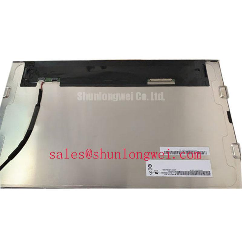
When unboxing an AUO G156HAN02.2 for a surgical navigation cart or ultrasound console retrofit, begin by inspecting the 40-pin eDP interface pins under magnification and verifying logic ground-to-VDD cold resistance before applying 3.3V power. Mechanical alignment checks and electrical boundary verifications must precede bench integration, particularly in medical diagnostic environments where visual artifacts directly impact image evaluation.
Surface Anti-Glare (AG) & Anti-Reflective (AR) Etched Coating for High Ambient Readability
Medical imaging environments expose displays to high-intensity overhead surgical lights and dynamic ambient glare. The AUO G156HAN02.2 utilizes an advanced wide-viewing-angle AHVA panel structure delivering symmetric viewing angles of 89°/89°/89°/89° (Left/Right/Up/Down at CR ≥ 10). Unlike standard Twisted Nematic (TN) panels that suffer from grayscale inversion and chromatic shift when viewed from lower angles or oblique cart positions, this symmetrical cone maintains optical fidelity across the active viewing area. The factory anti-glare surface treatment scatters specular reflections, preserving the panel's typical 1000:1 static contrast ratio and 400 cd/m² luminance rating without creating distracting hot-spots on low-key ultrasound acoustic sweeps.
Optical consistency across gray scales depends heavily on backlight stability. When tuning the constant-current driver for edge-lit WLED arrays, system engineers should adopt a PWM dimming frequency between 200 Hz and 1 kHz (Engineering Recommendation for pulse-width driver modulation). Operating within this window maintains linear duty-cycle luminance scaling down to low-light procedural settings, preventing audible inductor whistle in quiet operating theaters while completely avoiding the visual flicker artifacts that can disrupt camera recording or long-duration diagnostic review.
VESA vs. JEIDA Data Mapping Alignment & Even/Odd Channel Signal Integrity
The G156HAN02.2 relies on a 2-lane embedded DisplayPort (eDP) interface via a 40-pin terminal connector to receive 1920×1080 Full HD image data. Solid signal integrity across the high-speed differential pairs requires careful layout on the driving motherboard, specifically maintaining a tightly coupled 100-ohm differential characteristic impedance. Any mismatch along the flexible printed circuit (FPC) or carrier routing induces signal reflections, manifesting as horizontal sparkle, bit errors, or split-screen data displacement on the active pixel matrix.
⚠️ Field Alert: Never mate or unseat the 40-pin eDP interface cable while the system power supply is energized. The 3.3V logic supply rail sits directly adjacent to sensitive ground and auxiliary pins. Live insertion risks mechanical pin skewing, instantly bridging 3.3V into auxiliary or differential receiver lines. This burns the on-board surface-mount protective fuse or permanently punctures the timing controller silicon. System integrators must also verify that the logic supply rise time satisfies the standard window of 0.5 ms < t1 < 10 ms (Design Consideration for logic rail inrush control) to prevent power-on latch-up states.
Signal routing practices, differential line balancing, and timing protections are outlined in detail within The Ultimate Guide to Industrial TFT LCD Technology. Proper driver configuration ensures consistent data deserialization without odd/even channel phase lag.
Preventing Localized Light Guide Plate (LGP) Compression Warp on Dark Screen Fields
Display mechanical integration into diagnostic imaging enclosures requires strict adherence to physical boundary envelopes. The G156HAN02.2 features an outer dimension profile of 363.8 × 215.9 mm and an active display window of 344.16 × 193.59 mm. Because ultrasound diagnostic modes display deep black acoustic fields surrounded by subtle tissue echogenicity, the panel is sensitive to localized optical mura (clouding) caused by external mechanical pinch points.
| Parameter | Technical Specification | Field Verification Method |
|---|---|---|
| Screen Diagonal & Resolution | 15.6 inch / 1920×1080 (FHD) | Native pixel timing validation via eDP AUX |
| Active Area (W × H) | 344.16 × 193.59 mm | Bezel aperture mechanical clearance check |
| Outline Dimensions | 363.8 × 215.9 mm | Chassis structural mounting envelope |
| Luminance & Contrast | 400 cd/m² (Typ.) / 1000:1 | Center-point photometer / optical probe |
| Viewing Angles (L/R/U/D) | 89° / 89° / 89° / 89° (CR ≥ 10) | Off-axis color shift and chromaticity inspection |
| Interface & Power | eDP (2 Lanes, 40-pin) / 3.3V VDD | DMM voltage drop / 100Ω differential TDR test |
| Backlight Lifespan | WLED, 50,000 Hours (Typ.) | Thermal imaging of edge-lit LGP heat rail |
When securing the metal bezel within an aluminum chassis, apply a cross-pattern tightening sequence using M3 fasteners with torque restricted to 0.35–0.45 N·m (Design Consideration for industrial sheet-metal display housings). Overtightening pinches the internal light guide plate against the optical reflector films, causing localized stress-induced birefringence that appears as permanent white corner flares during dark-field clinical scanning. Adequate perimeter clearance and non-hardening damping gaskets isolate the internal light guide plate from enclosure warpage under thermal cycling, supporting the backlight's rated 50,000-hour operational lifespan (Official Datasheet Specification to 50% initial luminance).
Micro-Twist Mechanical Stress Fracture Prevention on Glass Substrate Driver Bumps
Field failures displaying localized vertical line defects or complete dark screens require a systematic isolation process to differentiate backlight driver faults from physical glass damage. When bench testing a suspect display, supply clean 3.3V logic power and deliver full-screen primary red, green, blue, black, and white test fields under controlled ambient light.
If the display presents a black screen while the host system reports active eDP handshaking, direct a high-intensity inspection flashlight at a 45-degree angle onto the outer polarizer. If faint diagnostic graphical elements remain visible beneath the surface, the liquid crystal layer and timing controller are operational, confirming the issue lies within the WLED driver rail or open-circuit LED strings. Conversely, sharp, single-pixel vertical lines running from edge to edge indicate mechanical stress fractures along the Chip-on-Glass (COG) driver micro-bumps, usually caused by chassis torsion or impact. When maintaining legacy medical carts and reviewing auxiliary touchscreen modules, engineers cross-referencing sub-display replacements for smaller secondary patient monitors frequently evaluate panels such as the LMS700KF01-001 alongside full-size primary diagnostic screens.