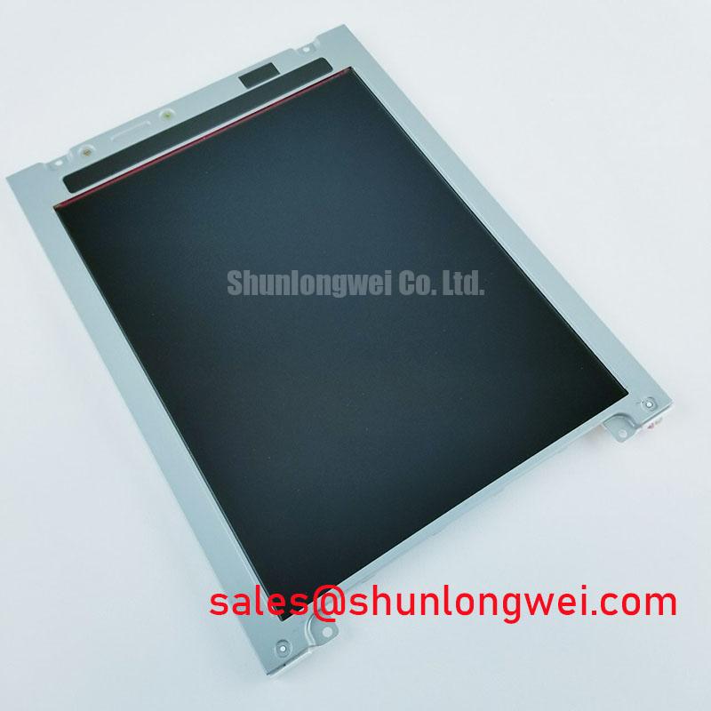


Content last revised on October 4, 2026
Checking Frame Lag and Image Smearing in Cold Facilities
When an HMI develops slow transitions after a cold start, compare the same moving test image at the affected temperature and after the assembly has stabilized in a controlled indoor environment. Increased liquid-crystal viscosity can slow pixel transitions at low temperatures (Design Consideration), but a sluggish image alone does not establish that the LM10V331 is operating within its specified temperature range. Confirm the applicable limit in the original panel documentation before using cold-room results to judge the module.
Keep the test image and video source unchanged between observations. If the entire interface pauses rather than individual transitions smearing, inspect the controller output and signal path as well as the panel. Record whether the symptom follows temperature, appears only on particular gray transitions, or remains present on a static image. Those distinctions help separate response-time behavior from intermittent data transfer without assigning a cause from appearance alone.
A dim screen calls for a different check. Verify the panel supply and the installed backlight drive circuit against the original equipment schematic, then compare commanded brightness with the light actually produced. The supplied product identification does not establish the LM10V331 backlight technology, drive current or rated brightness life; a published endurance figure for another display should not be transferred to it. If a visibly worn image remains after changing content, distinguish persistent optical retention from an unchanged source signal by disconnecting the video source only under the equipment’s prescribed shutdown procedure.
Power sequencing matters during that diagnosis. A white screen at startup or an image that lingers during shutdown can involve the timing of panel power, video data and backlight control (Design Consideration). Capture those signals at the equipment connectors and compare their order with the controller and panel documentation. The required delays are system-specific; changing them without checking both documents risks obscuring the fault rather than resolving it. For broader context on display behavior and selection, consult The Ultimate Guide to Industrial TFT LCD Technology.
Tracing Pixel Jitter and Horizontal Lines Near Motor Drives
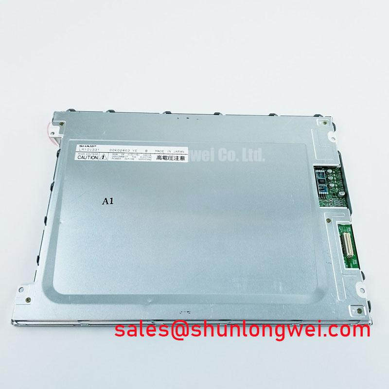
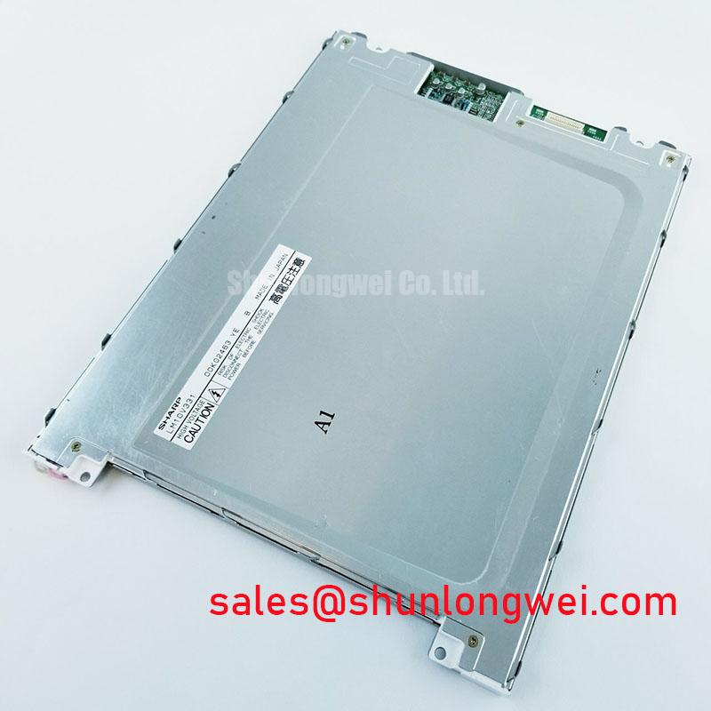
Disconnect the display assembly, then inspect the LM10V331 connector and cable for incomplete seating before treating a dark screen as a failed panel. The Sharp LM10V331 is identified as an industrial LCD/HMI panel in a TFT-LCD display module form factor (Official Factory Specification). Its supply voltage, interface pinout, active area, resolution, backlight requirements and operating temperature limits are not established by the available product parameters. Match those details to the original Sharp documentation and the equipment service record before applying power or ordering a replacement.
Before modifying shielding, observe whether horizontal lines or pixel movement coincide with a nearby motor drive changing state. Compare the image with the drive idle and active, and capture the display supply and source signals at accessible test points. Correlation is useful, but it is not proof of electromagnetic coupling: a loose connector, unstable panel supply or upstream graphics fault can produce similar symptoms.
Trace the cable from the controller to the LM10V331 without assuming its signalling standard. The available product parameters do not identify a TTL or LVDS interface, its clock limits, or its pin assignments. Confirm the interface in the original documentation before selecting a probe arrangement or evaluating clock integrity. Where the installed system uses a shielded display cable, inspect its termination and routing against the equipment design; shielding changes and common-mode suppression should be assessed on the complete assembly, not treated as guaranteed panel-level fixes (Design Consideration).
Connector handling deserves the same attention as signal quality. Inspect the mating surfaces for contamination or damage, check that the latch closes evenly, and look for strain where the flexible cable leaves the connector. A cable that works only when pressed or repositioned suggests an intermittent path, but the connector, cable and board pads each need examination. Avoid repeatedly flexing an unknown cable to “prove” a fault; use the original service procedure to determine whether it can be safely removed and reseated.
Field alert: Remove power and follow the equipment’s discharge procedure before disconnecting or reseating the display cable.
When comparing candidates during a repair, do not infer compatibility from an LCD category label. The LM190E08-TLG6 can be reviewed as a separate display reference, but its mechanical outline, interface, timing and optical characteristics must be checked independently against the LM10V331 installation. A matching connector shape alone does not establish interchangeability.
Preventing Mounting Stress and Dark-Field Mura
With the display unpowered, inspect how its frame sits in the equipment bezel. Look for uneven gaps, cable pressure behind the module and contact points that could load the viewing surface when the enclosure is closed. If a dark patch changes as the bezel is loosened, document that observation and check the mounting stack before condemning the optical assembly. It does not, by itself, identify a particular internal layer or manufacturing defect.
The available product parameters specify no LM10V331 outline dimensions, mounting-hole geometry or fastener torque. Use the original panel drawing and equipment mechanical specification for those limits. Tighten approved fasteners in a balanced sequence and check the displayed image after final enclosure assembly (Design Consideration); do not apply a generic chassis torque as though it were a Sharp rating. Verify that any gasket or retaining feature bears on the locations intended by the equipment designer rather than transferring load to the visible display area.
Brightness behavior should also be tested with the assembly fully installed. Step through the equipment’s normal brightness settings while displaying a uniform dark field and then a midtone image. Note flicker, uneven illumination or audible noise, and compare each observation with the backlight control signal and supply at the installed driver. The supplied LM10V331 parameters do not specify a PWM frequency, dimming method or backlight driver. Those values must come from the original panel and equipment documentation, followed by measurement in the actual system.
For power-path troubleshooting, treat other display products as distinct assemblies rather than presumed companion parts. The LM64P10 provides a separate display reference when reviewing service options; its electrical role and compatibility with the LM10V331 cannot be established from the model names. Confirm the installed driver board and its wiring directly before attributing an illumination fault to either component.
Separating Glass Stress, Backlight Faults and Persistent Line Defects
Run a controlled bench image sequence before disturbing the panel mounting: display full-screen red, green and blue from a known-good source, then a dark image. Record whether a line remains fixed in the same position, changes with the source, or appears only at certain brightness settings. A fixed line may point toward the display assembly, but cable contacts, controller output and power integrity still need to be checked before reaching a replacement decision.
For a screen that appears black, shine a flashlight across the viewing surface at an oblique angle while the system is commanded to show a recognizable image. A faint visible image can help distinguish absent illumination from absent image data (Design Consideration). This test is qualitative: ambient light, surface reflections and displayed content affect what can be seen. Follow it with electrical checks at the accessible supply and backlight connections using the original service documentation.
Inspect the module for twist introduced by its enclosure, particularly if the symptom appeared after installation or a chassis repair. Compare the image with the module supported as specified and with the enclosure assembled, without pressing on the glass. Persistent lines should not be labelled as driver-bond fractures from appearance alone; document the line pattern and test the upstream signal path first.
For a long-running HMI with static menus, vary the displayed content during evaluation to see whether a residual pattern fades, persists or originates in the video source. Any content-management change intended to limit retention belongs to the equipment designer and should be validated against the application’s display requirements. The available LM10V331 parameters do not establish a sunlight contrast rating or anti-glare coating, so railway passenger information terminals and cab displays are potential fit assessments only. Check their required legibility, enclosure, electrical interface and mechanical fit against verified panel documentation before approving the module for either installation.