Content last revised on October 4, 2026
Mitigating Gray-to-Gray Response Lag during Cold-Start Machine Power-Up
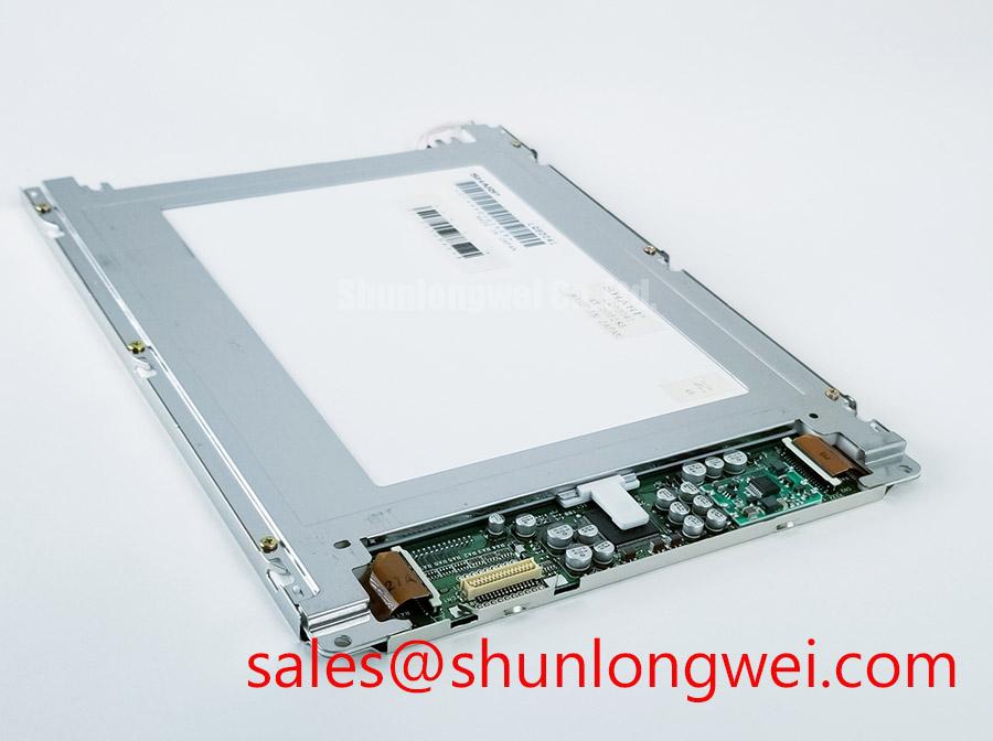
Inspect the AC043NA11-T1 connector and display face before installation, then compare the host wiring and mounting opening with the original equipment documentation. The verified product identity is an Ampire industrial-grade TFT-LCD display module. The supplied factory specifications do not establish its dimensions, electrical ratings, interface, optical performance or backlight type, so those details must be confirmed before a replacement is energized.
A cold display can appear slow even when its image data is correct. As liquid-crystal response changes with temperature, transitions between shades of gray may become more noticeable during machine startup. For the AC043NA11-T1, no verified operating-temperature range or gray-to-gray response-time value is available here. Maintenance staff should therefore compare cold-start behavior with the original equipment acceptance criteria rather than treating a particular lag as an Ampire specification.
Capture the startup sequence with a repeatable test image and note whether delayed transitions affect the entire active area or only a region. Check the equipment’s temperature reading and allow the enclosure to reach a stable condition before repeating the observation. A change in behavior as the assembly warms can inform the investigation, but it does not by itself isolate the panel: the video source, display controller and backlight controls also need review.
Design Consideration: In equipment exposed to large thermal swings, inspect the perimeter for visible seal damage and check for condensation before assessing image quality. A heater, if present in the host assembly, needs its own documented control sequence and clearance assessment; a heater strip must not be assumed to be part of this module. For harsh-environment evaluation methods, the Industrial Display & HMI Solutions guide provides broader enclosure and test context.
Electrical troubleshooting should begin with the original panel pinout and controller schematic. Do not infer an LVDS interface from the TFT-LCD description alone. If the documented host connection is differential, Design Consideration calls for checking pair routing, termination and timing at the installed cable length, especially near switching servo equipment. A nominal 100 Ω differential routing target is a common interface design consideration, not a verified AC043NA11-T1 requirement. The system engineer should establish the applicable impedance and skew limits from the actual interface documentation and measured signal margin.
Polarizer Durability and Optical Inspection under Direct Industrial Lighting
View the powered display with known test images from the operator’s normal position before judging it under overhead lamps or daylight. Move the light source or shade the screen briefly: a reflection that moves with the light points to a different investigation than a fixed mark in the image. Record observations with the protective cover and glazing installed, because enclosure surfaces can dominate what the operator sees.
The supplied specifications do not identify the AC043NA11-T1 liquid-crystal mode, viewing-angle limits, polarizer construction or anti-glare treatment. TN inversion and the broad viewing behavior associated with other LCD modes are useful comparison topics, but neither can be assigned to this panel without its factory optical data. Likewise, an apparent loss of contrast under direct light does not establish a defective polarizer until surface contamination, cover-window reflections, brightness settings and the video signal have been checked.
Design Consideration: For an operator who must read the screen at an angle, assess the assembled HMI from the actual seated and standing positions. Use the original equipment’s readability criteria for text, status colors and warning graphics. If a separate touch overlay is fitted, inspect its cover surface and bonding arrangement independently of the LCD. Glove response and operation with water on the surface depend on the specified touch technology and controller settings; neither capability is established by the AC043NA11-T1 module description.
Repeat an optical check after the equipment has stabilized from a cold start. This helps distinguish a transient response change from a persistent visibility problem without assigning an unsupported temperature threshold or response-time rating to the panel. Document the ambient conditions and viewing geometry so a later inspection can reproduce the comparison.
Checking Backlight Startup without Assuming a CCFL or LED Driver
Observe whether the image and illumination start together. If the screen appears dark, use the host service procedure to determine whether image data is present before changing any backlight hardware. A faint image, intermittent illumination or a blank screen can each have several possible causes; controller enable signals, cable seating, supply behavior and the display assembly should be checked against a known-good signal path where available.
The provided factory information does not establish whether the AC043NA11-T1 uses a CCFL inverter or an LED backlight driver. It also provides no ignition-voltage, dimming-ratio, brightness, contrast-ratio or service-life rating. CCFL striking-voltage figures and LED pulse-width-modulation settings must not be applied to this model by analogy. The system integrator should identify the required backlight supply and control sequence from the original panel documentation before connecting a driver.
Design Consideration: Where high-frequency drive electronics sit near the display harness, check grounding, cable placement and the controller waveform under the machine’s operating conditions. Audible noise or unstable brightness may warrant measurement at the documented driver connections, but neither symptom alone identifies its source. Any electromagnetic compatibility assessment belongs to the complete installed equipment; the display module’s product category does not establish system-level compliance.
For equipment used outdoors, evaluate readability with the actual cover window, shading and brightness control in place. Direct sunlight, reflections and accumulated dust can change the result substantially. Record a baseline image at the operator position rather than assuming a contrast figure measured in another optical setup will describe the installed HMI.
Flush-Mount Bezel Fit and Perimeter Gasket Shock Isolation
Dry-fit the AC043NA11-T1 and its mating enclosure parts before tightening the assembly. Check that the active area aligns with the viewing aperture, the connector has cable clearance and the bezel does not bear unevenly on the display face. The supplied factory specifications contain no verified outline dimensions, mounting-hole pattern or fastener torque, so the equipment drawing and Ampire mechanical documentation must control those checks.
Design Consideration: Bring fasteners down evenly using the host assembly procedure, then inspect a uniform dark test image for pressure-related bright or dark patches. If a patch changes when mechanical load is relieved, review bezel flatness, spacer height and gasket placement before assigning the observation to the LCD itself. Do not apply a generic fastener torque to an unverified mounting arrangement.
A perimeter gasket can support dust control and help manage contact between the display assembly and its enclosure, but its material, compression and sealing performance are properties of the complete design. Check for gaps, hardened sections and trapped debris during routine maintenance. After a washdown, a temperature change or a cold start, inspect the viewing window for moisture before attributing haze to the module’s optical layers.
For a heavy mining shovel or earthmoving-equipment telematics display, the AC043NA11-T1 can be considered only as a compatibility candidate until the original documentation confirms electrical interface, mechanical fit, visibility and environmental limits. The vehicle’s vibration isolation, sealing and touch performance are system-level questions, not verified characteristics of this LCD module.
Maintenance Note: Disconnect power before reseating the display cable, and check the enclosure gasket and ventilation path during the same inspection.