Content last revised on September 24, 2026
Thermal Cycling Degradation of Polarizer Adhesives and Sealant Gasket Integrity
| Product Model | M150XN05 V3 |
|---|---|
| Manufacturer | AU Optronics (AUO) |
| Product Category | Industrial Grade LCD/HMI Panel |
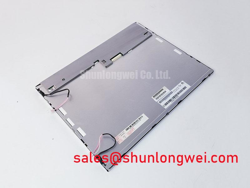
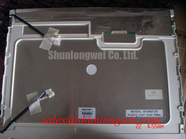
| Display Construction | TFT LCD Active Matrix Color Display Module |
| Specification Status | Official Factory Spec Verified |
Run a controlled cold start and warm recovery check while observing the complete active area for delayed image transitions, edge haze, contrast shift, or temporary unevenness. These observations help separate a temperature related optical response change from a signal source issue. The official factory information supplied for M150XN05 V3 confirms its TFT LCD active matrix construction, but it does not provide a verified operating temperature range, gray to gray response value, polarizer material specification, or perimeter seal construction. Those values should therefore remain tied to the documentation for the installed equipment rather than being assumed from a similar panel family.
At low ambient temperature, liquid crystal behavior can become visibly slower in many TFT LCD assemblies. This is a Design Consideration, not an official response time rating for this model. During a cold chamber evaluation, compare a known stable image pattern after power up with the same pattern after the panel and host enclosure have reached a stable temperature. Moving grayscale ramps, alternating black and white fields, and fine text edges can reveal temporary response lag more reliably than a static logo screen.
Inspect the visible perimeter area under diffuse illumination before and after cycling. Look for progressive edge discoloration, local lifting, trapped moisture appearance, or a contrast boundary that follows the bezel edge. These findings do not independently establish the condition of any internal adhesive or sealant feature, but they provide useful evidence for determining whether stress is concentrated at the display edge, mounting frame, gasket contact area, or enclosure opening.
Mechanical compression from the host bezel deserves equal attention. A rigid bezel can transfer enclosure expansion and contraction directly into the glass edge or display border. An Engineering Recommendation is to evaluate the panel inside the actual retention structure, with the same fastening arrangement, support rails, and front gasket used in service. A loose bench test cannot reproduce pressure points created by an uneven mounting face or enclosure twist.
For installations exposed to vibration, salt laden air, or changing external temperatures, engineers should evaluate the panel as part of the complete sealed console assembly. The display itself is not a certification claim for the surrounding enclosure. Confirm enclosure sealing, drainage paths, grounding continuity, and connector retention at the system level.
Cold response should also be examined alongside the incoming video waveform. An apparently slow or partial screen refresh can arise from video timing instability, incorrect interface mapping, supply sequencing, or a physical connection issue. The diagnostic sequence is to document the optical symptom, capture the signal behavior at the host interface, and then compare the result with a known good console channel where available.
LVDS Timing, Pixel Clock, and Skew Compensation at the Installed Interface
Probe the active differential video pairs at the host side connector while the display shows a stable color field, then compare waveform symmetry and activity across all expected channels. Split images, repeated vertical regions, unstable color planes, or intermittent white screen behavior can indicate an interface problem, although no single visual symptom proves one cause. Inspect the cable path, connector lock condition, supply sequence, grounding, and host timing source before attributing the issue to the panel.
The official data provided for M150XN05 V3 does not confirm connector pin count, LVDS channel arrangement, input voltage, pixel clock, or JEIDA and VESA mapping. Do not interchange a panel based only on display size, mechanical fit, or a connector that appears similar. The system integrator should verify the required supply voltage, connector assignment, mapping format, and power sequence from the original panel documentation and the host controller documentation.
In industrial equipment with long harness routes or concentrated electrical noise, differential signal integrity remains a Design Consideration. Matched routing, stable reference planes, controlled pair impedance, and minimal pair to pair timing mismatch help maintain the receiver margin. The actual routing target and permitted skew must be established by the source controller, cable construction, and installed panel interface, then validated with switching and image tests on the completed equipment.
Use a sequence that begins with connector inspection under magnification. Confirm that the flexible cable is fully seated, aligned squarely with the connector body, and retained by its intended latch mechanism. Next, examine the cable for sharp folds, abrasion at chassis openings, and repeated bend points near a moving service door. Then observe power up and power down behavior while recording whether the video source becomes valid only after the panel supply is stable. This method helps identify whether the fault follows the panel, cable, controller board, or power control path.
Some service screens show a normal image only after a reboot. That result should not be treated as evidence of a panel defect without checking the host sequence. A display can retain an abnormal appearance after an interrupted power event when the controller, timing source, and panel are not returning to their intended order. Verify sequence behavior with the actual equipment schematic and oscilloscope capture rather than relying on a visual inspection alone.
For more context on panel interfaces, image artifacts, optical behavior, and practical display troubleshooting, review The Ultimate Guide to Industrial TFT LCD Technology. It is useful when separating interface integrity questions from optical and mechanical display observations.
Heat Spreader Placement and Thermal Interface Review Along Narrow Display Edges
Capture a thermal image of the installed display bezel, controller area, cable exit, and adjacent power hardware after the console has reached its normal duty condition. The purpose is to locate localized heating around the display perimeter and surrounding assembly, not to infer an internal thermal design that has not been specified for M150XN05 V3.
The verified factory data identifies this item as a TFT LCD active matrix color display module, but does not establish a backlight type, brightness rating, heat spreader arrangement, thermal resistance, LED lifetime value, L70 value, or B50 value. These figures must not be assigned to this model without the corresponding factory document. If the host assembly includes a backlight driver, assess that driver and its thermal environment as separate system elements.
Heat gathered near narrow display edges can come from nearby processors, driver boards, power conversion stages, enclosure solar loading, or an obstructed ventilation path. A Design Consideration is to spread heat through the host structure where mechanical clearances permit, while avoiding concentrated clamp force on the display border. Any thermal interface material, rail, or chassis contact arrangement must be reviewed against the equipment mechanical drawing so that it does not impose bending stress on the panel.
Long duration static HMI screens require attention even when there is no obvious thermal fault. Repeated stationary graphics, high contrast borders, and permanently displayed alarm icons can leave temporary image retention on some LCD systems. This is an application behavior to evaluate with the intended user interface, not a guaranteed performance characteristic of this panel. Screen management, interface color choices, and periodic content movement are decisions made by the equipment designer.
When a console uses a front window or anti glare treatment, inspect the entire optical stack as installed. Reduced readability can result from surface contamination, a scratched cover lens, condensation, backlight weakness, an incorrect image setting, or strong reflections from the surrounding environment. Do not claim a sunlight contrast value or anti glare coating property for M150XN05 V3 unless those features are confirmed in the applicable factory document.
Record thermal observations together with supply stability and image behavior. A bright but intermittent image may point toward a connection, driver, or power issue, while a stable image with uneven apparent illumination may warrant closer review of the complete display assembly. The inspection should preserve the distinction between measurable evidence and unverified internal assumptions.
Incoming Benchtop Inspection for Display Surface, Cable Interface, and Line Defects
Display solid red, green, blue, white, black, and mid gray test fields across the full screen before installation, recording any persistent pixel anomaly, line irregularity, local brightness variation, edge shadow, or color nonuniformity. This primary color procedure gives technicians a repeatable incoming inspection record for the M150XN05 V3 display module and avoids relying on a boot logo that may conceal small defects.
Follow the color test with a dark screen inspection using a flashlight held at an oblique angle. A shallow viewing angle can reveal surface scratches, pressure marks, contamination beneath a protective layer, and areas where the apparent image differs from surrounding pixels. This observation can help distinguish a backlight related condition from a signal or active area issue, but it cannot by itself identify a particular internal bonding technology or microfracture mechanism.
The supplied factory information does not confirm chip on glass construction, tape automated bonding construction, anisotropic conductive film details, anti glare coating, contrast ratio, or high ambient readability specification. Avoid assigning line defects to a named internal process without supporting evidence. Instead, document the defect orientation, whether it changes after cable movement, whether it appears on every test color, and whether it is present with a known good controller source.
Inspect the flexible cable and connector under magnification after every bench test. A cable that is slightly offset, incompletely inserted, or bent tightly at its exit point can create intermittent image artifacts that resemble a panel fault. Repeated service access can also stress the connector latch or cable bend region, especially where the cable passes close to a chassis edge.
💡 Bench Tip: Disconnect system power, control electrostatic handling, and keep the flexible cable perfectly level during insertion so the connector lock closes evenly across its full width.
For a reliable acceptance record, photograph each full screen test pattern, note the host controller used, record the observed connector condition, and retain the results with the equipment work order. If the intended application is a marine radar or navigation bridge console, evaluate the completed console for enclosure sealing, vibration control, viewing angle, glare, and salt exposure resistance as system level requirements. The display module should be assessed within those conditions rather than being credited with unverified environmental or optical ratings.