

Content last revised on September 28, 2026
Suppressing Pixel Jitter and Horizontal White Lines Induced by Adjacent 400V Motor Drives
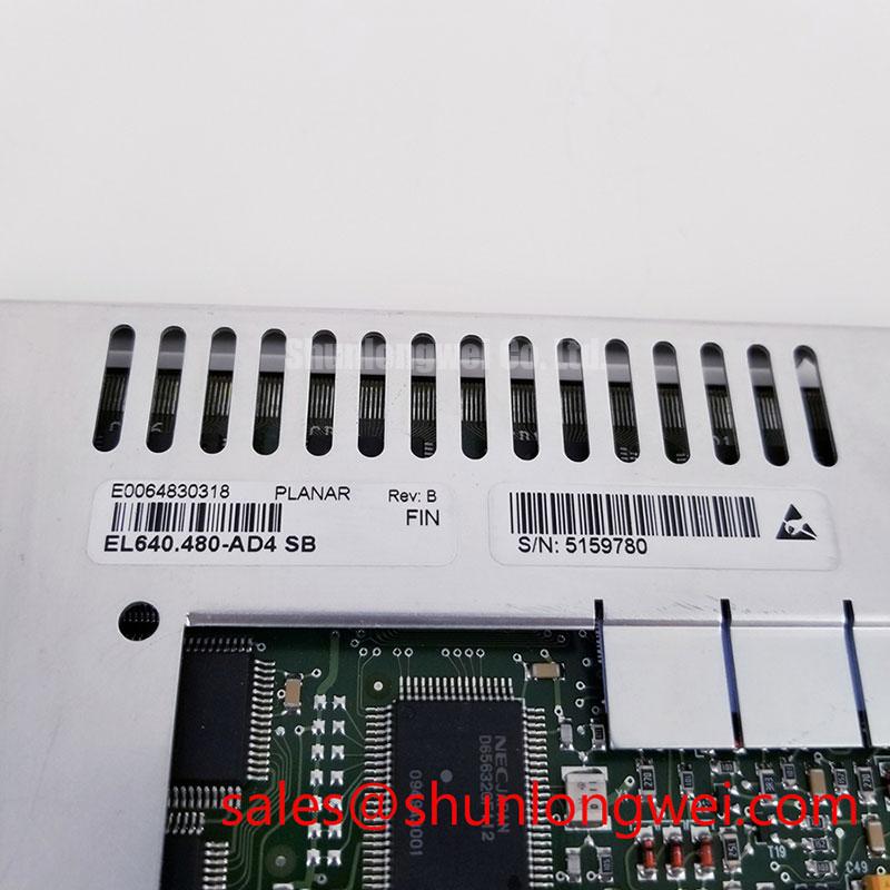
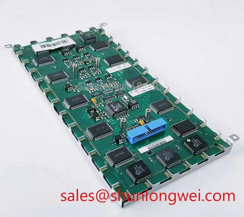
When an EL640 replacement is evaluated inside an operator station located near variable frequency motor drives, begin with the signal path rather than changing display settings. Record the original cable construction, connector orientation, shield termination, and controller output format. The system integrator should verify whether the host uses LVDS, TTL, or another display interface from the original documentation; the EL640 product context supplied here does not confirm a specific interface standard or pin assignment.
A 360-degree shielded FFC or LVDS cable arrangement can reduce the exposed area of the high-speed return path, but the shield termination must match the enclosure bonding strategy. A shield connected at an unsuitable point can create a new common-mode current path, particularly where the display cable runs beside motor output conductors. Cable routing should therefore separate switching power conductors from the pixel clock and data pairs, with the final arrangement checked during motor acceleration, deceleration, and fault-reset events.
Common-mode ferrite components may be considered where conducted interference is observed on the display link. Their impedance profile must be evaluated against the actual differential data rate and common-mode spectrum; selecting a part solely from its nominal impedance can reduce signal margin or create additional edge distortion. An oscilloscope comparison between the known-good signal path and the EL640 installation can help distinguish clock integrity problems from a panel or controller fault.
Direct sunlight testing also belongs in the acceptance procedure for a field monitoring terminal. A requirement such as contrast above 500:1 at 50,000 lux should be treated as a system validation target, not as a confirmed EL640 factory rating. Measure the complete assembly with its cover glass, anti-glare surface, window, and enclosure in place. The anti-glare treatment should be checked for reflected hot spots and loss of fine text detail at the intended viewing angle.
💡 Pro Tip: Disconnect power before removing or inserting the display cable, and verify shield continuity after reassembly.
High-Humidity Storage Margins and Delamination Prevention Protocols
For a hazardous petrochemical operator station, storage and transport conditions can be more damaging than normal powered operation. Moisture exposure should be assessed at the complete display assembly level because the available EL640 data does not confirm a humidity rating, seal construction, adhesive system, or qualified thermal cycle range. A 60°C and 90% RH storage evaluation may be useful as a project test condition, but it must not be presented as an official Planar environmental specification without the applicable datasheet.
Inspect the perimeter, optical stack, connector region, and bezel interfaces after conditioning. Look for edge whitening, bubbles, local haze, seal separation, corrosion products, and changes in the appearance of uniform test screens. A gradual return to room conditions should be used before electrical testing so that surface condensation is not mistaken for an internal panel defect.
Sub-zero operation requires a separate review. Liquid crystal response can become slower as temperature falls, which may appear as gray-to-gray image trailing during moving graphics or rapid screen updates. This is a design consideration for the host display controller and user interface, not a confirmed EL640 response-time specification. Designers should verify the required operating range, warm-up behavior, and image acceptance criteria using the original panel documentation and a representative enclosure.
Where a heater strip is considered, its control loop should be evaluated with the panel’s optical stack, mounting frame, and nearby temperature-sensitive components. Localized heating can create brightness non-uniformity or mechanical stress if heat is concentrated around one edge. The system engineer should determine heater placement, control limits, and warm-up sequencing through environmental testing rather than applying an assumed value to the display module.
For replacement planning, the NL192108JC18-03ND may be reviewed as a same-size or same-resolution replacement candidate where its own mechanical, optical, and electrical documentation confirms compatibility. It should not be treated as a direct substitute for EL640 until connector geometry, active area, mounting points, timing, and backlight requirements have been matched.
Full-Screen Primary Color AOI Screening for Stuck Sub-Pixels and Uniformity
Incoming inspection should use full-screen red, green, blue, white, black, and mid-gray patterns generated by a known-good controller. The first pass checks for permanently bright or dark sub-pixels. The second examines background uniformity and edge-to-center luminance. The third repeats the inspection after a controlled warm-up period, because temperature and drive stabilization can alter the appearance of slow or marginal defects.
A 45-degree flashlight inspection in a darkened area can help separate an external surface mark from a defect beneath the front surface. If a dark region changes with the angle of illumination, inspect the cover, polarizer surface, and optical path before attributing it to the backlight. If the region remains fixed on controlled color fields, compare it with the signal path and perform a second-panel comparison. This approach avoids assigning a single cause to every line, shadow, or inactive pixel.
COG-related line defects should be handled as an inspection concern rather than a presumed diagnosis. A narrow vertical or horizontal line can originate from the panel drive path, controller timing, connector contact, mechanical pressure, or a damaged flex interface. Light mechanical probing should not be used as a repair method. Record the defect location, screen pattern, temperature, cable condition, and whether the defect changes when the input source is replaced.
LED backlight life and luminance decay also require source-specific confirmation. A statement such as 50,000 hours to 50 percent brightness must not be assigned to EL640 unless it appears in the applicable Planar documentation and specifies the test conditions. For procurement qualification, measure luminance at defined drive settings and ambient conditions, then retain the baseline for later comparison. A constant-current driver can improve repeatability, but the compatible driver, dimming method, and control polarity must be verified from the panel documentation.
Digital boundary-scan methods can support controller-board diagnostics, but the JTAG IEEE 1149.1 reference should not be treated as evidence that the EL640 panel itself exposes a JTAG test port. Similarly, partial discharge testing applies to relevant high-voltage insulation systems and is not a substitute for LCD pixel, backlight, or interface verification.
Optical Luminance Degradation and CCFL-to-LED Retrofit Evaluation
Before considering a CCFL-to-LED modernization path, identify the backlight technology fitted to the original EL640 assembly. The supplied product information does not confirm whether this model uses CCFL, LED, a particular inverter, or a defined dimming interface. The system integrator should verify the required supply voltage, backlight connector, enable signal, dimming polarity, and protection behavior from the original panel documentation.
CCFL retrofits can involve high-voltage ignition and inverter behavior that is not interchangeable with a constant-current LED driver. A quoted cold-ignition range such as 1500 to 1650 Vrms must be treated as an application-specific engineering value unless confirmed by the original backlight documentation. Clearances, insulation, cable routing, acoustic behavior, and enclosure bonding should be reviewed by the responsible system engineer.
For an LED modernization, a constant-current driver with PWM dimming may be evaluated to control brightness, but the acceptable frequency range, duty-cycle linearity, startup sequence, and minimum pulse width are determined by the selected driver and panel interface. A proposed range such as 200 Hz to 1 kHz is a design investigation range only, not an EL640 specification. Verify visual flicker with a camera-based method and verify audible noise at the selected operating point.
Brightness measurements should be taken at the center and defined edge locations using the same optical geometry each time. Record the display window, cover glass, ambient illumination, drive setting, and temperature. This creates a practical degradation record without inventing field failure rates, MTBF values, or a guaranteed half-life for the EL640.
For long-duration operator-station projects, the broader Industrial Display and HMI Solutions engineering reference can be used alongside the panel’s original documentation when reviewing enclosure sealing, optical readability, maintenance access, and environmental test planning. Any Zone-2 installation must still be assessed as a complete certified assembly; the LCD module alone does not establish explosion protection, EMC compliance, or hazardous-area approval.