

Content last revised on May 26, 2026
AUO M150XN05 V1: An In-Depth Engineering Review for Industrial Display Integration
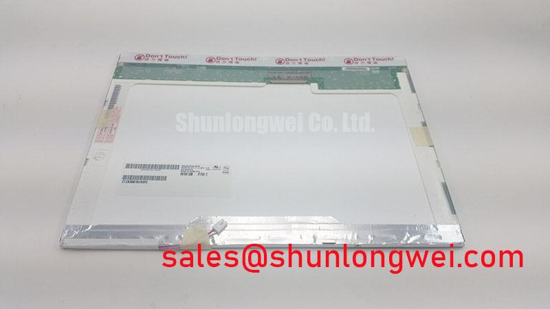
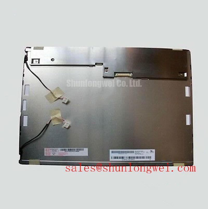
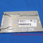
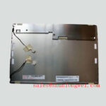
The AUO M150XN05 V1 is a 15.0-inch a-Si TFT-LCD module engineered for longevity and consistent performance in demanding operational environments. Centered on a robust mechanical design and stable optical characteristics, this display provides a reliable XGA visualization platform. It delivers a specification blend of 1024x768 resolution, a 250 cd/m² brightness level, and a 30,000-hour backlight lifetime. Key benefits include its durable construction with a hard-coated (3H) surface and a straightforward TTL interface for simplified system integration. For engineers evaluating displays for industrial control panels or legacy system upgrades, a primary concern is operational reliability within a specific temperature range; the M150XN05 V1 is specified for stable operation from 0 to 50°C. With its focus on physical resilience and proven CCFL backlight technology, this model is a workhorse solution for applications where operational uptime is paramount.
Key Parameter Overview
Decoding the Specs for Mechanical and Environmental Stability
The technical specifications of the M150XN05 V1 underscore its suitability for integration into industrial equipment where mechanical fit and operational consistency are primary design considerations. The panel's physical dimensions and defined operating parameters are critical for ensuring long-term system reliability.
| Parameter Group | Specification | Value | Engineering Insight |
| Display Characteristics | Screen Size | 15.0 inches | Standardized size for broad compatibility with industrial enclosures. |
| Resolution | 1024(RGB)×768, XGA | Provides clear, sufficient detail for typical HMI and control applications. | |
| Brightness | 250 cd/m² (Typ.) | Adequate for indoor industrial environments with controlled lighting. | |
| Contrast Ratio | 400:1 (Typ.) | Ensures clear differentiation between graphics and text on-screen. | |
| Mechanical & Environmental | Outline Dimensions (W×H×D) | 326 × 249 × 12.5 mm | A defined physical footprint simplifies mechanical design and integration. |
| Weight | 1.10 kg (Typ.) | The mass must be factored into mounting and structural support calculations. | |
| Operating Temperature | 0 ~ 50 °C | Defines the ambient thermal range for guaranteed operational performance. | |
| Storage Temperature | -20 ~ 60 °C | Specifies safe non-operational temperature limits for transport and storage. | |
| Interface & Backlight | Signal Interface | TTL (2 ch, 6-bit) | A well-established interface ensures compatibility with a wide range of controller boards. |
| Backlight System | 2 pcs CCFL, 30,000 hours lifetime | The long-life CCFL backlight supports applications requiring extended operational hours. An external driver is required. |
Download the M150XN05 V1 datasheet for detailed specifications and performance curves.
Application Scenarios & Value
System-Level Benefits in Industrial HMI and Control Systems
The M150XN05 V1 is best suited for deployment in stable, indoor industrial environments where data clarity, reliability, and long-term availability are more critical than cutting-edge optical performance. Its design provides a dependable foundation for essential visualization tasks.
A key engineering challenge in designing HMIs for manufacturing lines or process control stations is ensuring the display can withstand the ambient conditions of the factory floor while providing a clear interface for operators. The M150XN05 V1 addresses this directly with its specified operating temperature range of 0 to 50°C. This parameter isn't just a number; it gives engineers a defined thermal budget. It confirms the display will maintain stable optical performance without flickering or image degradation inside an enclosure that may experience moderate temperature fluctuations due to surrounding machinery. The antiglare surface with a 3H hard coating further enhances its value by ensuring readability under typical factory lighting and providing resistance to incidental contact. For systems requiring similar durability in a slightly different form factor or with different interface requirements, models like the M150XN07 V2 may offer alternative integration paths.
Frequently Asked Questions (FAQ)
What is the primary implication of the 0 to 50°C operating temperature range for system design?
This range confirms the M150XN05 V1 is engineered for typical industrial control room and factory floor environments. System designers must ensure their enclosure's internal ambient temperature does not exceed this 50°C limit to guarantee the display's specified performance and lifespan.
Does the M150XN05 V1 include a backlight driver?
No, the datasheet explicitly states that an external backlight driver is required for the dual CCFL system. This allows engineers to select a driver that best fits their system's power supply and control architecture.
How does the TTL interface impact integration?
The 75-pin TTL (2 ch, 6-bit) interface is a standard for this class of display, offering straightforward integration with many industrial motherboards and single-board computers that feature a compatible TTL output. It simplifies the electrical design compared to more complex interfaces, making it a good choice for cost-effective or legacy system upgrades.
Technical Deep Dive
A Closer Look at the CCFL Backlight and its Impact on Longevity
While LED backlights have become common, the Cold Cathode Fluorescent Lamp (CCFL) system in the M150XN05 V1 brings specific, valuable characteristics for certain industrial applications. Its most significant engineering value lies in its proven track record and predictable performance over a long operational life, specified at 30,000 hours. This is analogous to choosing a well-established industrial motor over a newer, less field-tested design for a critical application. The 30,000-hour rating provides a solid basis for maintenance scheduling and calculating total cost of ownership. It means the display's illumination source is designed to last for over 3.4 years of continuous, 24/7 operation, a crucial metric for systems in factory automation or monitoring where downtime is costly. Furthermore, the color spectrum produced by CCFL technology is well-understood and stable, ensuring consistent color representation for HMIs where specific colors may indicate critical system statuses.
For engineering and procurement teams, sourcing a replacement or planning a new system build requires a clear understanding of the component's capabilities. If you are evaluating the M150XN05 V1 for your application, please contact our technical sales team to discuss your specific project requirements.