Content last revised on October 18, 2026
TX18D200VM0EWA Identification and Installation Checks
- Record the panel identification marking and compare it with the installed display before removing cables.
- Inspect the FFC or display connector for incomplete locking, contamination, pin displacement, and mechanical strain.
- Check the panel mounting frame for uneven pressure, bezel contact, and fastener loading around the active area.
- Confirm the display supply, backlight arrangement, signal format, and power sequencing from the original equipment documentation.
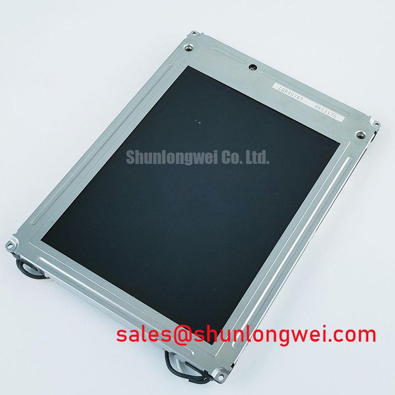
The TX18D200VM0EWA is identified as a KOE / Hitachi TFT-LCD Active Matrix Color Display Module. It may be evaluated for use in precision electronic test and measurement instruments, provided the replacement process matches the original electrical interface, mechanical envelope, and display timing.
| Product category | LCD display module |
| Manufacturer | KOE / Hitachi |
| Display construction | TFT-LCD Active Matrix Color Display Module |
| Application reference | Precision electronic test and measurement instruments |
Radiated Emissions Evaluation and Backplate Grounding
Pixel jitter, horizontal noise bands, or unstable measurement graphics near a variable-frequency motor drive should first be treated as a system-level interference problem rather than as proof of a panel defect. Inspect the display cable route, shield termination, backplate bonding, and the relationship between the display harness and switching power conductors. Shielding on an FFC or LVDS cable assembly can help reduce interference coupling when its termination and chassis reference are integrated according to the equipment grounding architecture.
A backplate star-ground approach can help avoid uncontrolled return-current paths, but the exact bonding method is determined by the instrument enclosure, protective-earth arrangement, cable construction, and EMC test plan. At high frequencies, bonding impedance must also be considered; star grounding alone does not establish emissions compliance. Designers should keep high-speed display conductors away from motor-drive output wiring and should verify the result with near-field probing or conducted and radiated emissions testing. Ferrite components may be evaluated as a system-level suppression measure when the interference path has been identified; they should not be treated as an automatic accessory of this LCD module.
Direct sunlight and strong bench lighting also expose optical weaknesses that may be mistaken for electronic noise. The integrator should evaluate contrast stability, anti-glare performance, viewing angle, and readability at the actual instrument window and lighting level. The public product context does not establish a guaranteed contrast ratio or coating specification for this model, so those optical requirements belong in the incoming inspection and application qualification plan. General industrial TFT display practices can be compared with the product information published by Winstar Industrial TFT-LCD Modules.
Preventing Localized Display Compression and Dark-Field Nonuniformity
Dark-field mura, corner shading, or a localized bright patch often becomes visible after a panel is installed in a replacement bezel. The mechanical inspection should focus on whether the bezel, gasket, rear support, and connector harness apply uneven pressure to the display assembly. Similar overall dimensions do not by themselves confirm interchangeability of mounting holes, support lands, bezel clearance, or optical stack height.
Use a cross-pattern installation sequence only when it matches the equipment maker’s mechanical instructions. Fastener torque must be taken from the panel or chassis documentation. The panel should be observed at uniform dark, gray, and white test fields after installation, with attention to changes caused by bezel pressure rather than immediately attributing every luminance variation to the display electronics.
Signal integrity also deserves a separate check. The installed controller may use TTL, LVDS, or another interface, but the correct format, clock relationship, data hold requirement, and power sequence must be taken from the original panel documentation and controller design. If the replacement is being compared with TX18D203VM2BAA, compare the electrical interface, pinout, supply requirements, connector position, timing requirements, mounting geometry, and backlight control before treating it as a direct replacement.
⚠️ Field Alert: Remove equipment power and allow stored energy to discharge before inserting or removing the display cable.
Suppressing Localized Thermal Gradients to Reduce Optical Aging and Color Shift
Thermal mapping around the narrow edges of the display is more useful than judging panel temperature by touch. Measure the frame, rear support, backlight region, and nearby power-conversion components while the instrument operates in its normal enclosure. A localized hot area can produce optical drift, adhesive stress, or uneven aging, but the cause may be the enclosure or driver board rather than the LCD module alone.
Aluminum spreader rails may be evaluated when the mechanical design creates a repeatable edge hot spot. Their dimensions, contact pressure, insulation, and attachment method must be selected from the enclosure thermal model. They should not block vents, load the active area, or transfer chassis distortion into the display. Claims concerning PMMA light-guide construction, yellowing resistance, L70, B50, or backlight lifetime are not established by the baseline product description and should be confirmed through the applicable technical documentation or a controlled qualification test.
High-EMI factory environments also require attention to differential signal routing where a differential interface is used. Keep paired conductors together, control reference continuity, and avoid abrupt routing changes near switching nodes. A differential impedance target such as 100 Ω ± 10% may be relevant to a particular LVDS system, but it is a system interface requirement rather than an established TX18D200VM0EWA module specification. The commissioning engineer should check eye quality, common-mode behavior, and clock stability at the display connector under the real enclosure and load conditions.
For equipment such as a precision electronic test instrument, long static display periods can also create residual-image concerns. Use the host controller’s screen-management functions where appropriate, vary noncritical graphical elements during extended idle periods, and verify recovery behavior with the actual panel and backlight setting.
Thermal Cycling Degradation of Polarizer Adhesives & Sealant Gasket Integrity
Thermal cycling evaluation should begin with the complete display assembly, not only the LCD cell. Record startup behavior, image uniformity, connector retention, bezel stress, and backlight response at the equipment’s specified temperature limits, while respecting the panel’s documented ratings. Sub-zero operation can alter liquid-crystal response and may produce visible lag, but the acceptable response profile depends on the panel specification, controller timing, and application requirements.
Perimeter seals, optical adhesives, polarizer surfaces, and enclosure gaskets should be inspected after environmental exposure for lifting, haze, edge contamination, or loss of compression. The available product information does not establish a guaranteed operating range of −30°C to +85°C, a GTG response value, or a sealant qualification level for the TX18D200VM0EWA. Any equipment qualification criteria must be checked against the panel’s documented capabilities before testing.
Backlight evaluation should separate driver behavior from the panel’s optical output. Measure luminance at defined drive conditions, check thermal rise at the backlight region, and compare startup and warmed-state readings. A claim such as 50,000 hours to 50 percent brightness is a lifetime rating that requires a published source and defined test conditions; it should not be assumed for this model.
For a replacement project, the most useful acceptance record combines connector retention, display timing, optical uniformity, thermal response, and mechanical fit. Engineers planning broader enclosure or HMI reliability work can consult Industrial Display & HMI Solutions for related integration considerations.