Content last revised on September 23, 2026
G190ETN01.2 AUO Industrial LCD Panel Identification and Incoming Checks
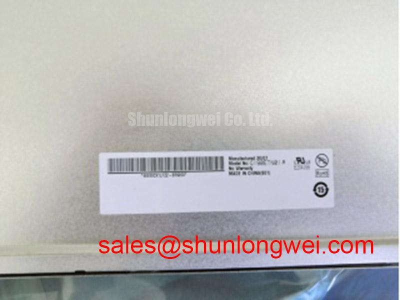
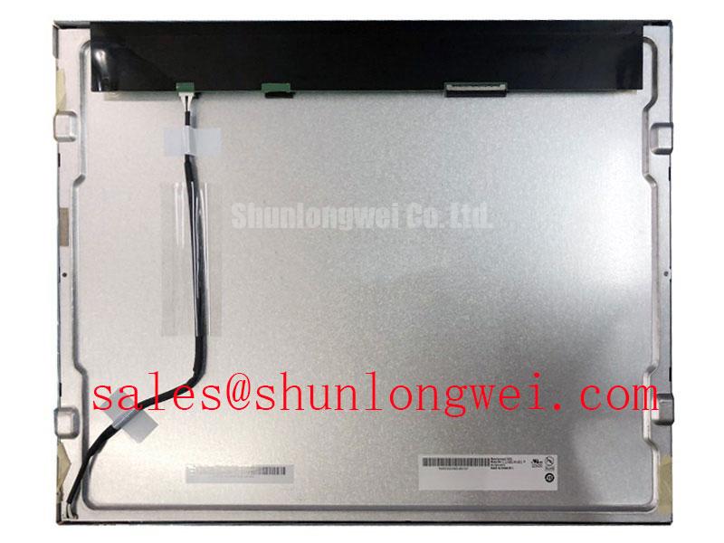
Begin the service inspection by comparing the G190ETN01.2 nameplate and connector arrangement with the original display documentation before applying power. The supplied product information identifies this unit as an AUO Industrial Grade LCD/HMI Panel with a TFT-LCD Display Module construction and an Official Factory Spec Verified status. Those are the confirmed product-level facts available for this listing; interface voltage, resolution, luminance, viewing angle, backlight type, connector pinout, and operating temperature should be confirmed against the original panel documentation for the equipment under repair.
During incoming inspection, check the glass edge, mounting frame, flexible cables, connector locks, and visible driver-board areas for transport stress. Keep the protective packaging in place until the mechanical fit and electrical identity have been checked. A cold resistance measurement can help identify an accidental short on the host-side power harness, but it does not establish whether the display itself is electrically functional. Use the known-good signal path and the equipment service manual as the reference for any powered test.
| Parameter | Confirmed information |
|---|---|
| Model | G190ETN01.2 |
| Manufacturer | AUO |
| Product category | Industrial Grade LCD/HMI Panel |
| Package or enclosure form | TFT-LCD Display Module |
| Specification status | Official Factory Spec Verified |
When a replacement display is being evaluated for a marine radar or navigation bridge console, enclosure sealing, optical cover design, salt-air protection, connector retention, and thermal conditions remain system-level responsibilities. The model should not be treated as a drop-in replacement until the original panel’s electrical and mechanical records have been matched.
Differential LVDS Interface Checks, Timing, Pixel Clock, and Skew Compensation
Start compatibility work at the interface rather than at the image symptom. Count the host connector contacts, identify the panel-side cable orientation, and compare the signal naming in the original documentation. A similar connector shape does not confirm identical pin assignment. The system integrator should verify the required supply voltage from the original panel documentation instead of assuming a common logic rail.
For an LVDS installation, route the differential pairs as controlled-impedance structures according to the host board design rules and preserve pair symmetry through the connector transition. Equal electrical path length, consistent reference-plane continuity, and limited stub length are useful Design Considerations for reducing clock-to-data skew. The appropriate characteristic impedance is determined by the transmitter, receiver, cable, and PCB stack-up; it should be verified from the system design documentation rather than presented as an AUO specification for this model.
JEIDA and VESA mapping must also be checked. Incorrect color-bit ordering can produce an image that appears active while showing incorrect color levels, split images, or unstable synchronization. When the panel documentation does not clearly identify the mapping, compare the replacement against the original cable and transmitter configuration before changing firmware or FPGA settings.
Backlight control requires the same discipline. The available dimming method, enable polarity, current regulation, and allowable control waveform must be confirmed from the host system and original display documentation. PWM frequency and duty-cycle behavior are system integration variables, not confirmed factory parameters for the G190ETN01.2 in the supplied data. If visible flicker, audible noise, or brightness nonlinearity appears, observe the enable and dimming signals with an oscilloscope while comparing them with a known-good assembly.
💡 Pro Tip: Keep the LVDS pairs closely coupled and route them with matched electrical paths through the cable and board transition to reduce pixel-clock timing uncertainty.
Radiated Emissions Evaluation and Backplate Grounding
The display module should be assessed as part of the complete console, not as an independent EMC-certified assembly. In a cabinet containing variable-frequency motor drives or other high-current switching equipment, first separate image noise from power integrity problems by checking the panel supply, chassis bonding, cable routing, and signal reference arrangement under the same operating condition that produces the fault.
A continuous shield termination at the cable entry can reduce unwanted common-mode current when it is compatible with the host enclosure and connector construction. Backplate bonding points should be evaluated for paint, oxide, mechanical contact pressure, and cable return paths. Star-grounding language can be misleading when several high-frequency currents share the same metalwork, so the final bonding method should be validated with conducted and radiated measurements on the assembled equipment.
Ferrite components may be considered on the cable or backlight path when testing identifies common-mode interference, but their impedance behavior depends on frequency, current, placement, and the surrounding return path. Selecting a part solely by its nominal impedance can move the resonance rather than remove the disturbance. CISPR Class A or Class B performance belongs to the completed equipment and its installation; this LCD module should not be described as independently holding either system-level classification.
Backlight aging should be evaluated from the actual backlight specification and driver operating condition. A constant-current driver, thermal environment, dimming profile, and enclosure temperature all affect optical output over time. No model-specific half-life or MTBF value is asserted here because such data is not included in the supplied official parameter set. For broader panel selection principles, engineers can consult The Ultimate Guide to Industrial TFT-LCD Technology.
The host power network also deserves inspection. MOV placement, fuse coordination, transient clamping, and return-current routing should be selected from the console’s measured surge environment and applicable safety design rules. Bootstrap capacitors, diode recovery, and parallel positive-temperature-coefficient devices belong to the external driver or power stage; they are not confirmed internal features of the G190ETN01.2.
Backlight Conditions and Insulation Testing
Do not infer the backlight technology from the model number or from the appearance of the connector. The system integrator should verify whether the original assembly uses a particular backlight architecture, its driver requirements, and its high-voltage insulation arrangement from the original panel documentation. Applying a legacy inverter or a constant-current driver without that verification can create an electrical mismatch even when the image interface appears compatible.
For any service test involving elevated backlight voltage, use the equipment manufacturer’s approved insulation procedure, guarded test fixtures, and discharge controls. The test voltage, ramp rate, dwell time, clearance, and acceptance criteria must come from the applicable product and safety documentation. They should not be assigned as universal values for this AUO module. Disconnect power before removing or inserting display cables, and confirm that stored energy has been discharged.
Clock jitter and data hold behavior should be checked at the receiver during the actual temperature range specified by the equipment design. An oscilloscope comparison between the original and replacement assemblies can help distinguish a transmitter timing issue from a cable, grounding, or power integrity issue. If the panel is being considered for a harsh marine radar or navigation bridge console, enclosure temperature, condensation control, salt-air exposure, and service access must be reviewed by the equipment designer.
For the surrounding display topology, the LM190E08-TLG6 can be reviewed as a separate display-related solution. It should be treated as an independent product evaluation, not as a stated substitute or guaranteed companion for the G190ETN01.2.
Mechanical Stress Checks, Glass Handling, and Field Diagnosis
Before tightening the display into a bezel, place it on a clean, level support surface and confirm that the mounting points do not force the frame into twist. The glass substrate and bonded driver areas require even mechanical support; a housing that is flat when unloaded can distort after fasteners, seals, or a protective window are installed. Mounting force, gasket compression, and screw sequence are Design Considerations that must follow the original equipment drawing.
A three-stage image check is useful during bench diagnosis. Display a primary-color field, then a neutral field, and finally a detailed text or grid pattern. Observe the panel directly and through the installed cover glass. A dark region that changes with viewing angle or directional illumination may involve the backlight path, while a fixed line, column, or color discontinuity can require inspection of the signal path and bonded driver region. These observations are indicators for further measurement, not standalone proof of a single failure mechanism.
A flashlight held at an oblique angle can reveal uneven illumination or shadow boundaries during a dark-screen check. Use low mechanical contact and avoid pressing the glass or flexible bonded areas. If the symptom changes when the frame is touched, repositioned, or clamped, stop the test and inspect mounting stress before continuing electrical troubleshooting.
Cold-environment testing should account for liquid-crystal response changes, host-controller timing, condensation, and heater control where the equipment includes a thermal management system. The supplied factory data does not establish a guaranteed response-time range or low-temperature operating limit for this listing. Engineers should verify those values from the panel’s original technical documentation before approving operation in a sub-zero enclosure.
When local replacement planning requires a different mechanical or electrical candidate, the M185XW01 VE may be reviewed as a separate compatibility candidate. Connector mapping, active area, mounting geometry, optical performance, supply requirements, and controller configuration must be checked independently before procurement or installation.