

Content last revised on October 14, 2026
CCFL Inverter Striking Voltage & Ignition Debugging
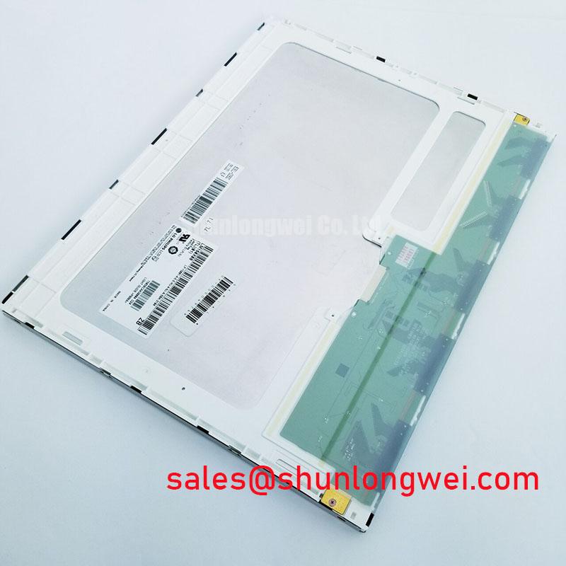
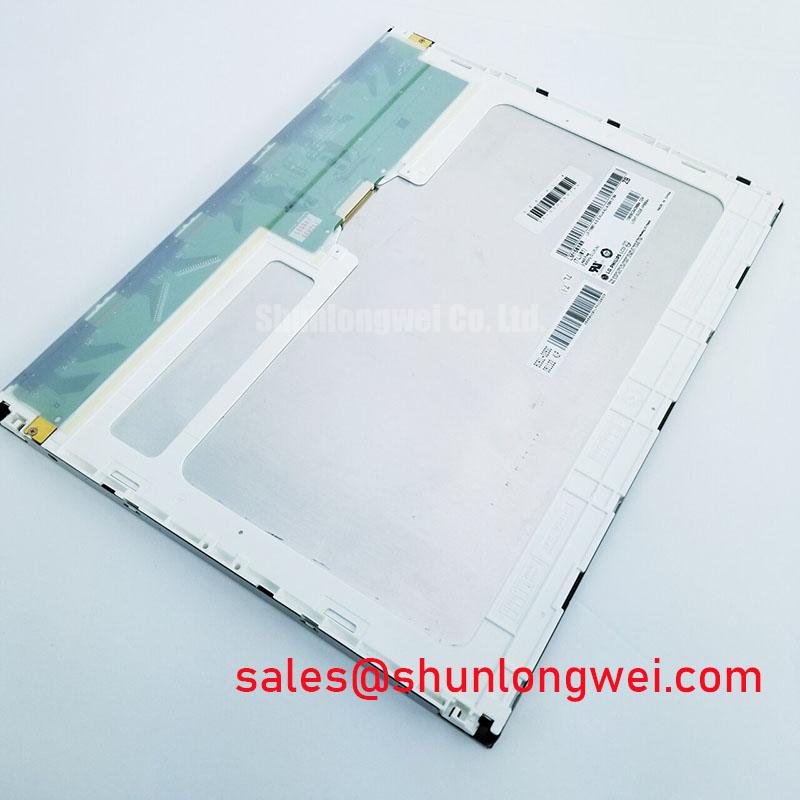
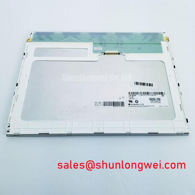
With the panel disconnected from the machine, inspect the backlight connector, inverter harness, and chassis bonding before applying power; this first check separates a display-module fault from an inverter, cable, or grounding problem. The LM150X08-TLC1 is identified as an LG Display TFT-LCD active matrix color display module, so the replacement assessment should begin with the original panel interface, backlight arrangement, and mechanical envelope.
If the existing AGV or forklift telematics assembly uses a CCFL backlight, a cold-start failure can originate in the resonant inverter rather than the LCD image path. Listen for intermittent acoustic buzz only after confirming that the high-voltage section is correctly enclosed and connected. A weak ignition attempt, unstable brightness, or delayed illumination should be compared with the known-good inverter waveform and harness condition instead of being assigned to the panel alone.
Constant-current LED drivers are a different architecture and cannot be treated as a direct electrical substitute for a CCFL inverter. The system integrator should verify the required supply voltage, backlight type, connector assignment, enable logic, and dimming method from the original panel documentation before adapting the assembly. PWM dimming behavior, if used by the host equipment, should be evaluated for visible flicker, acoustic interaction, and brightness linearity under the actual telematics display enclosure.
Outdoor warehouse aisles and loading areas can produce strong reflections across an unprotected display surface. Contrast measurements under direct ambient illumination are a system-level optical evaluation, not an automatic specification of this model. Check the fitted cover lens, anti-glare treatment, viewing direction, and enclosure shading together, because a panel that appears acceptable on a bench may lose legibility when sunlight reaches the screen at a shallow angle.
Full-Screen Primary Color AOI Screening: Stuck Sub-Pixels & Background Uniformity Audit
Run a full-screen red, green, blue, white, and black image sequence through the original controller before approving the display for service. The purpose is to distinguish isolated sub-pixel behavior, broad luminance non-uniformity, connector contamination, and backlight distribution effects. Record observations at the same brightness setting and viewing distance used during the equipment inspection.
A 45-degree flashlight inspection across a black screen can reveal localized shadows, edge leakage, contamination, or pressure marks that are difficult to see in a normal front view. Move the light slowly across the surface rather than shining directly into the viewer’s line of sight. A defect that follows the backlight area may require investigation of the optical stack or housing, while a line that remains fixed relative to the active matrix can point toward the display drive path or bonded edge region. This is a diagnostic distinction, not a single-cause rule.
For an AGV or forklift display, check the screen after the unit has reached its normal operating condition. Cold-start appearance, warmed-up uniformity, and brightness at the lowest practical setting should be compared because temperature and enclosure airflow can alter the visual impression. PWM frequency and duty-cycle behavior belong to the host driver evaluation; the panel should be assessed with the actual controller rather than a generic signal source.
When a replacement is being considered, compare the same image files, connector orientation, active-area alignment, and bezel registration. The LM150X08-TL02 can be evaluated as a separate same-size-class replacement candidate, but electrical and mechanical compatibility should be established against the original equipment documentation before procurement or installation.
Chassis Fastener Tightening to Reduce Mounting-Induced Optical Mura
Install the panel into the chassis with the bezel supported evenly around its perimeter, avoiding any condition where one corner carries the frame load. Localized compression can create dark-field mura, edge shading, or a non-uniform appearance that is mistaken for a panel optical defect. The actual cutout, mounting-hole pattern, spacer height, and bezel envelope must be matched to the equipment drawing.
As a general Design Consideration, the chassis team should select fastening torque according to the mounting hardware, bracket materials, and applicable panel and equipment documentation, then validate it during mechanical trials. Use a cross-pattern sequence, check that the bracket is not twisted, and inspect the screen again with a dark test image after final tightening.
Thermal expansion and vibration can expose a mounting problem that is not visible during a short bench test. For rugged telematics equipment, the bracket should constrain movement without transferring concentrated stress into the display perimeter. Sealing materials must also be compressed consistently; a displaced gasket can admit dust or moisture while simultaneously loading one side of the bezel.
Signal integrity belongs in the same installation review. Where the host uses TTL or LVDS transmission, compare clock quality, data hold behavior, cable routing, and ground reference across the expected temperature range. These are controller-and-harness characteristics rather than confirmed product ratings. The system engineer should verify the complete signal path with the installed cable length, connector retention, and enclosure routing.
⚠️ Maintenance Note: Inspect the cooling air path and perimeter gasket during scheduled service so dust buildup or gasket displacement does not create uneven thermal or mechanical loading.
Normally White TN Grayscale Inversion Mitigation & Optimal Viewing Direction Alignment
Set the operator viewing direction before judging grayscale performance on a normally white TN display. TN optical behavior can vary with vertical angle, and grayscale inversion may appear when the operator looks above or below the intended axis. For an AGV or forklift console, place the display so the normal seated or standing eye position remains within the validated viewing direction of the complete assembly.
Do not substitute a general IPS or MVA viewing-cone assumption for the actual LM150X08-TLC1 installation. A wide-angle panel specification, when applicable to another model, does not establish the optical behavior of this model. Evaluate grayscale steps, warning colors, and fine text from the operator’s normal position, then repeat the check with the protective lens, gasket, and bezel installed.
Anti-glare treatment can improve readability under high ambient illumination, but surface texture may also soften small characters or reduce perceived contrast. The final evaluation should therefore include the host graphics, cover lens, ambient reflections, and brightness control rather than relying on a panel-only observation. For industrial HMI optical and interface context, the Winstar Industrial TFT-LCD and OLED Display Modules reference provides useful industry background, while the TFT-LCD technology overview explains the underlying active-matrix display principle.
Condensation control is equally important during temperature transitions. Allow the enclosure, display surface, and controller to reach a stable condition before making optical judgments after moving equipment between a cool store and a warm operating area. The integration team should validate sealing, ventilation, and any required environmental control as part of the finished HMI assembly. Additional system-level guidance is available in Industrial Display & HMI Solutions, particularly when reviewing dust protection, thermal paths, and long-term enclosure serviceability.