

Content last revised on October 13, 2026
Radiated Emissions Evaluation (CISPR Class A/B) and Backplate Grounding
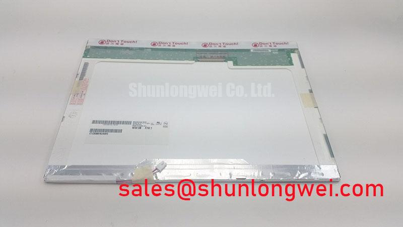
Isolate equipment power before disconnecting the display harness and inspecting its latch, cable routing, and mounting contact points; record whether the reported defect appears during startup, after warm-up, or only when nearby equipment switches. For the B141XG09-V5 from AUO, that distinction helps separate a connection or installation problem from a repeatable display fault without disturbing the optical assembly prematurely.
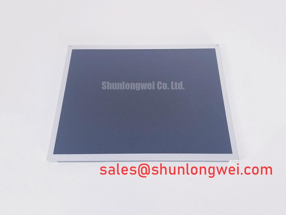
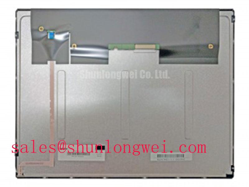
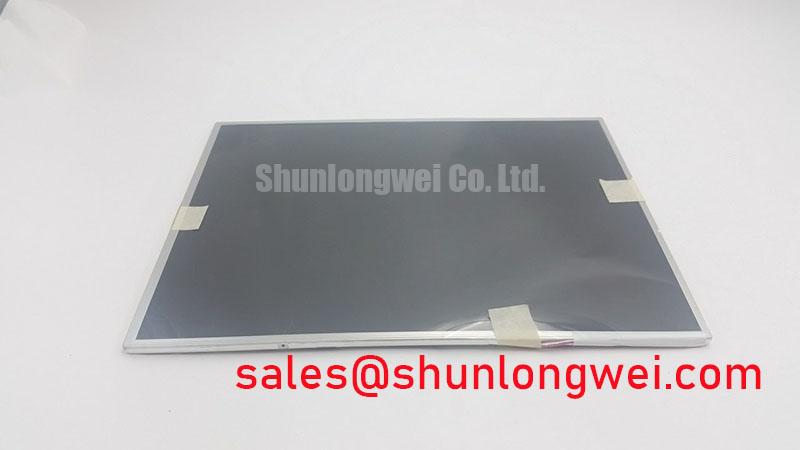
The product identity is a TFT-LCD Active Matrix Color Display Module, presented for industrial LCD/HMI panel evaluation. Match the complete model suffix when preparing a replacement assessment. At the compatibility checkpoint, consult the model-specific datasheet for supply voltage, interface pinout, timing, backlight requirements, dimensions, and operating limits. These electrical and mechanical details determine interchangeability; the industrial application category alone does not establish environmental qualification or medical-device suitability.
Correlate pixel jitter and horizontal noise bands with equipment switching before modifying the B141XG09-V5 cable assembly. As a Design Consideration, compare the image with the suspected interference source inactive, then active, while keeping the displayed pattern unchanged. Inspect the connector shield, chassis bonding surfaces, and cable path for discontinuities or routing alongside noisy power conductors. A symptom that follows switching activity warrants an interference investigation, but does not establish its coupling mechanism.
Where the host uses a shielded display harness, evaluate shield termination at the enclosure entry and connector shell. Circumferential shield contact can reduce an exposed termination path, subject to the connector and enclosure design. Do not treat multi-point bonding and star grounding as interchangeable prescriptions: high-frequency shield bonding and circuit-reference management serve different purposes. The final arrangement belongs to the equipment grounding design, and CISPR Class A or Class B performance must be assessed on the complete assembly.
Confirm the actual interface before measuring transmitter timing. For a documented LVDS connection, examine differential signal quality at the receiver while checking clock stability, pair routing, and the transmitter’s timing requirements. For a documented parallel interface, compare setup and hold behavior with the applicable receiver specification. Repeat relevant checks across the intended equipment temperature range. Ferrite suppression is an Engineering Recommendation only when measurements identify a common-mode path; its placement and characteristics require system-level verification.
Power sequencing deserves the same attention as signal integrity. Capture panel power, interface activity, and backlight enable during startup and shutdown, then compare their order with the approved timing requirements. Driving signal pins into an unpowered receiver can create an unintended current path. A white startup screen or lingering shutdown image should prompt checks of sequencing, controller initialization, and rail decay rather than an immediate panel diagnosis.
Optical Luminance Degradation Curve & CCFL-to-LED Modernization Retrofit Pathways
Record luminance under repeatable conditions before describing a B141XG09-V5 as dim: use the same test image, brightness command, instrument position, ambient lighting, and stabilization procedure. Compare center brightness and spatial uniformity separately. Reduced output, slow brightening, flicker, and audible driver noise can involve different parts of the display power chain; each observation needs correlation with supply behavior and backlight control signals.
A CCFL-to-LED retrofit is a system modification, not an established feature or approved upgrade for this model. First identify the installed backlight and its documented drive requirements. If a conversion is being considered, evaluate optical fit, illumination distribution, thermal loading, dimming behavior, and electrical separation from the panel electronics. Ignition voltage, PWM range, and service-life claims must come from the selected hardware documentation and supporting tests, not from generic backlight expectations.
As an Engineering Recommendation, inspect brightness-control behavior across the host’s usable command range while observing the driver supply and output with suitable instruments. Do not assume that an acoustic buzz proves a failing lamp or that a stable supply rules out driver trouble. A replacement driver also needs compatible enable logic, fault handling, and shutdown behavior. Match these functions to the host schematic before changing the illumination subsystem.
The LQ9D152 provides a separate display-product reference when reviewing associated display and power requirements; it should not be treated as a B141XG09-V5 backlight driver or a confirmed same-topology companion. For manufacturer context, AUO Corporation provides information about its display technologies. Neither reference establishes a retrofit approval for this panel.
Protect the flexible harness from repeated movement during servicing. As a Design Consideration, retain the intended routing, avoid creases at connector exits, and provide strain relief without pulling against the latch. Inspect cable seating after closing the enclosure, because a harness that looks secure on an open bench can shift when the cover is installed. Flex life and allowable bend geometry belong to the cable specification.
Full-Screen Primary Color AOI Screening: Stuck Sub-Pixels & Background Uniformity Audit
Display full-screen red, green, and blue patterns on the B141XG09-V5, then inspect white, black, and neutral-gray backgrounds for defects that the primary colors do not reveal clearly. Keep the host output settings fixed and record defect position, persistence, and dependence on brightness. For an automated optical inspection workflow, use consistent camera exposure and lighting so that inspection settings do not create apparent changes in uniformity.
Judge persistent points and lines against the applicable acceptance criteria rather than an invented pixel threshold. Compare the same pattern through a known-good signal path where practical. A line defect can involve the controller, harness, connector, or panel assembly; visual appearance alone does not identify an internal bonding failure. Avoid pressing on the bezel or flexing the module to make a defect disappear, since that changes mechanical loading and can obscure the diagnosis.
A gently directed external light can help reveal whether an image remains present when illumination is absent. This is a qualitative diagnostic aid, not proof of a particular backlight fault. Where the image is faintly visible, continue checking illumination enable, driver power, and the documented load. Where no image is visible, assess controller output and panel power as well; the observation does not isolate the failed part.
For replacement assessment, the LQ123K1LG03 is a comparison candidate, not a verified direct replacement. Compare active area, mounting geometry, connector location, interface mapping, timing, and illumination requirements before considering substitution. When evaluating surgical-navigation or ultrasound diagnostic display equipment, engineers should also verify the host’s image-performance requirements and applicable equipment approvals; a panel substitution does not inherit them automatically.
Long-lived static screens deserve an image-retention check. As a Design Consideration, compare a neutral background before and after the host’s normal static-screen exposure, then observe recovery under changing content. Where the application permits, screen blanking or content movement can reduce prolonged static patterns. Distinguish reversible retention from persistent defects through observation rather than calling every residual image permanent burn-in.
Diffuser Film & Prism Sheet Thermal Buckling Prevention under Continuous Full-Duty Operation
Inspect gasket contact and frame clearance before tightening the B141XG09-V5 into its enclosure. Uneven compression can transfer localized stress into the display assembly and contribute to edge brightness changes or visible mura. As a Design Consideration, support the module at its intended mounting points, keep sealing pressure uniform, and assess the finished image after fastening. Do not use additional screw force to compensate for a misaligned bracket or oversized gasket.
Measure enclosure temperature distribution during sustained operation before adding heat-spreader rails. Any added thermal path must accommodate assembly clearance and expansion without loading the optical stack. Optical films in LCD backlights redistribute light; the general principles are described in Diffuser Optics. That background does not identify this model’s internal film arrangement or materials, and it does not establish a thermal limit.
Inspect perimeter seals for displacement and compression changes without opening the optical stack as routine maintenance. Dust ingress, trapped contamination, and mounting stress can produce different uniformity patterns. Maintenance Note: Periodically inspect enclosure airflow paths and gasket seating, with power isolated before touching the display harness. After moving equipment from a cold area into warmer humid air, allow conditions to stabilize before energizing a potentially condensed assembly.
Evaluate readability in the finished enclosure under the intended ambient lighting, including reflections from any protective window. Bright-room contrast, surface treatment, and LED lifetime metrics cannot be assigned to B141XG09-V5 without supporting specifications. For broader enclosure checks, Industrial Display & HMI Solutions offers an integration reference rather than a certification standard. After thermal stabilization, repeat the uniformity inspection and confirm that cable restraint, gasket pressure, and frame clearance remain unchanged.