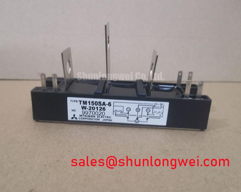
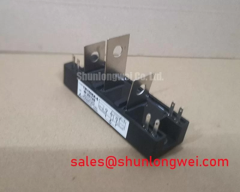


Content last revised on October 7, 2026
Assembly Integrity & Layout Architecture: Multi-Bridge Evaluation for TM150SA-6
With the rectifier isolated and its DC link discharged, measure resistance across each disconnected power path and compare the readings with an undamaged position in the same assembly. A persistent low-resistance reading warrants further isolation of the module and surrounding circuit; an in-circuit reading alone cannot distinguish a failed thyristor from a parallel path. Inspect terminal faces, cable lugs and mounting hardware for heat marks or uneven seating before removing the unit.
For a proposed six-pulse or twelve-pulse bridge, trace the installed schematic to establish where each TM150SA-6 sits, how its gates are driven and how bridge currents combine. The 150 A rating is a module rating, not a kiloampere output rating for an assembled rectifier. In a twelve-pulse system with an interphase transformer, current sharing depends on transformer design, firing balance and branch impedance. These are system Design Considerations to verify under load, not properties guaranteed by the module rating.
Record the existing terminal arrangement and mechanical fit before evaluating a replacement. SKT340/18E can be reviewed during a broader power-stage comparison, but its electrical function, ratings, footprint and connections require independent checking; it should not be treated as a drop-in equivalent. ⚠️ Field Alert: Apply mounting torque specified for the actual hardware and assembly, rather than inferring a torque value from the TM150SA-6 voltage and current ratings.
Benchtop Waveform Tuning: Off-State Voltage Stress on TM150SA-6
Capture voltage across the thyristor during commutation and compare the trace with gate-drive timing and the DC-link waveform. A rising off-state voltage coincident with unintended conduction calls for checks of the firing circuit, wiring and transient suppression path; the waveform alone does not establish which one is responsible. The 600 V rating sets the stated device voltage limit, while measured switching peaks determine whether the installed circuit approaches that boundary.
An RC snubber or series saturable reactor is a system-level Design Consideration where commutation produces excessive voltage rise or current rise. Select and validate those components from measured waveforms, operating conditions and their own ratings rather than assigning component values from the TM150SA-6 nameplate. Check any MOV for coordination with the expected transients and inspect its connection path; a MOV is not a substitute for verifying repetitive voltage stress at the module terminals.
For a short-circuit protection review, compare the installed semiconductor fuse’s published clearing and pre-arcing I²t data with the thyristor’s applicable surge limits and the circuit’s available fault current. No fuse coordination table or surge-current limit is established by the supplied TM150SA-6 ratings, so neither safe fault interruption nor a post-surge restart interval can be inferred here. SSIL2890S46C is another device to assess against its own documentation when reviewing the surrounding power-stage topology, not an assumed part of this module’s gate circuit.
Transient Dynamics & Electrical Design: Junction-to-Heatsink Heat Dissipation in TM150SA-6
Inspect the removed module’s contact imprint and the heatsink surface for gaps, contamination or uneven compound spread. Clean and prepare the mating surfaces using the assembly’s approved method, then check that tightening seats the package evenly without visible distortion. An isolated package does not, by itself, establish the assembly’s electrical isolation rating or thermal resistance.
During a controlled load test, record heatsink temperature near the mounting position and compare phase currents and temperature trends across equivalent bridge positions. The 150 A rating cannot be converted into an allowable heatsink temperature without operating conditions and the relevant thermal data. Where a power stage also cycles between charging and discharging, assess both duty directions; thermal cycling deserves attention, but no service-life estimate follows from the supplied specifications. For broader system-level fault and reliability considerations, see the Power Electronics Masterclass while keeping its IGBT-specific guidance distinct from thyristor data.
TM150SA-6 Thermal-Electrical Optimization: Practical Gate Trigger Tuning
Probe the gate-to-cathode firing waveform at the installed connection and compare it with the firing command and current onset on each comparable bridge position. An absent or irregular pulse may point to the driver, wiring or synchronization circuit as well as the module. The supplied specifications do not state a gate-current threshold, pulse rise-time requirement or holding-current value, so a proposed firing scheme must be validated against the applicable module documentation and measured circuit behavior.
Where phase-controlled rectification is used, check firing-angle consistency alongside input-current waveforms and the equipment’s harmonic requirements. For a high-current green hydrogen electrolyzer DC rectifier, this is a compatibility assessment of the complete bridge, transformer, controls and cooling system, not a claim that TM150SA-6 was specified for that equipment. If an existing controller uses an initial pulse followed by a holding portion or repeated firing pulses, verify reliable turn-on at the actual operating extremes without prescribing a pulse shape from the module’s 600 V and 150 A ratings alone.