


Content last revised on January 30, 2026
FM50DY-10 IGBT Module: Technical Data Sheet Analysis for Power Applications
Engineering Overview of the FM50DY-10
A Datasheet-Driven Look at a 500V, 50A Dual IGBT
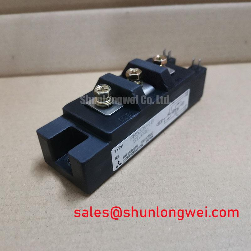
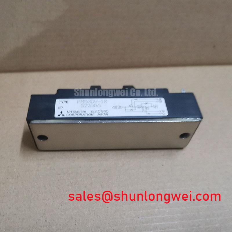
The Mitsubishi FM50DY-10 is a dual IGBT module designed for robust performance in medium-power switching applications. It delivers a core set of specifications focused on reliability in industrial environments. With ratings of 500V and 50A, and a power dissipation capability of 170W, this module provides a proven foundation for power conversion circuits. Its key engineering benefits include a simplified half-bridge topology and predictable thermal behavior, crucial for long-term operational stability. This module is specifically engineered to address the challenge of implementing a reliable inverter leg for 200-240V AC line applications. For systems requiring higher voltage blocking capabilities, such as those on a 480V line, the CM150DY-24H provides a 1200V rating.
Application Scenarios & Value
System-Level Benefits in Motor Drives and Power Supplies
The FM50DY-10 is best suited for applications where straightforward design and durability are paramount. Its integrated dual-IGBT (half-bridge) configuration makes it an excellent choice for building the inverter stages of small to medium-sized Variable Frequency Drives (VFDs) and AC servo drives. What is the primary benefit of its integrated design? It significantly reduces component count and simplifies the PCB layout compared to using discrete IGBTs, which in turn can minimize stray inductance and improve electrical performance.
In a typical VFD application for a 2.2kW motor on a 220V AC line, the module's 50A current rating provides sufficient headroom to handle both continuous load and startup inrush currents. The central engineering challenge in such a design is managing heat generated from switching and conduction losses. The module's well-defined thermal resistance is a critical parameter that allows engineers to design an effective cooling system, ensuring the junction temperature (Tj) remains within safe limits for long-term reliability. Its proven design also finds use in general-purpose inverters and switched-mode power supplies (SMPS) where cost-effectiveness and a history of reliable field performance are key decision factors.
Key Parameter Overview
Decoding the Specs for Thermal and Electrical Design
The performance of the FM50DY-10 is defined by its electrical and thermal characteristics. The following parameters, sourced directly from the official datasheet, are critical for system design, simulation, and thermal modeling.
| Absolute Maximum Ratings (Tc=25°C) | |
|---|---|
| Collector-Emitter Voltage (Vces) | 500V |
| Gate-Emitter Voltage (Vges) | ±20V |
| Collector Current (Ic) | 50A |
| Maximum Collector Dissipation (Pc) | 170W |
| Operating Junction Temperature (Tj) | +150°C |
| Electrical and Thermal Characteristics (Tj=25°C) | |
| Collector-Emitter Saturation Voltage (VCE(sat)) | 2.7V (Max) at Ic=50A |
| Turn-On Time (ton) | 1.0µs (Typ) |
| Turn-Off Time (toff) | 1.5µs (Typ) |
| Thermal Resistance (Rth(j-c)) per IGBT | 0.5°C/W (Max) |
| Thermal Resistance (Rth(j-c)) per Diode | 1.0°C/W (Max) |
Frequently Asked Questions (FAQ)
How does the VCE(sat) of 2.7V impact the thermal design for the FM50DY-10?
A higher VCE(sat) directly results in greater conduction losses, which are converted into heat (Power Loss = VCE(sat) × Collector Current). The 2.7V maximum value means that at full 50A load, each IGBT can generate up to 135W of heat from conduction alone. This makes an efficient thermal management system, including proper heatsink selection and mounting, absolutely critical to prevent the junction temperature from exceeding its 150°C limit and to ensure system reliability.
What is the primary advantage of the dual IGBT configuration in the FM50DY-10?
The main advantage is design simplification for inverter circuits. A dual or half-bridge configuration integrates two IGBTs and two free-wheeling diodes into a single package. This allows engineers to build one leg of a three-phase inverter with just one module, or a full single-phase inverter with one module. This reduces assembly complexity, saves board space, and can lead to more predictable performance by minimizing the parasitic inductance between switches compared to using separate discrete components.
Application Vignette: Ensuring Reliability in a Compact VFD
A Practical Look at Thermal Design
Consider an engineer designing a compact Variable Frequency Drive (VFD) to be housed in a sealed NEMA enclosure. The key challenge is not just electrical performance but ensuring the system can operate reliably without overheating. The FM50DY-10, while electrically suitable, presents a thermal puzzle due to its 2.7V VCE(sat). The engineer's primary task is to design a heatsink that can dissipate the calculated power loss while fitting within the enclosure's tight confines.
Here, the module's specified maximum thermal resistance (Rth(j-c)) of 0.5°C/W is the cornerstone of the solution. Think of thermal resistance like the wall thickness of a coffee thermos; a lower number means heat can escape more easily. Using this value, the engineer can precisely calculate the maximum allowable case temperature (Tc) to keep the junction temperature (Tj) safely below 150°C. This calculation dictates the required performance of the heatsink (Rth(c-a)), ensuring that even under worst-case load conditions, the system remains thermally stable. By basing the design on this clear datasheet parameter, the engineer moves from estimation to a predictable, reliable thermal solution, guaranteeing the VFD's long-term operational life.
Technical Inquiries
For detailed technical specifications, application notes, or to assess the suitability of the FM50DY-10 for your specific design, please consult the official Mitsubishi Electric documentation or contact our technical support team for further engineering data.