

Content last revised on September 12, 2026
Mitigating Gray-to-Gray (GTG) Response Time Escalation during Cold-Start Machine Power-Up
Before connecting the replacement display, inspect the mating cable, connector latch, perimeter gasket contact, and mounting points for contamination, uneven pressure marks, or moisture residue that could affect image uniformity or signal continuity.
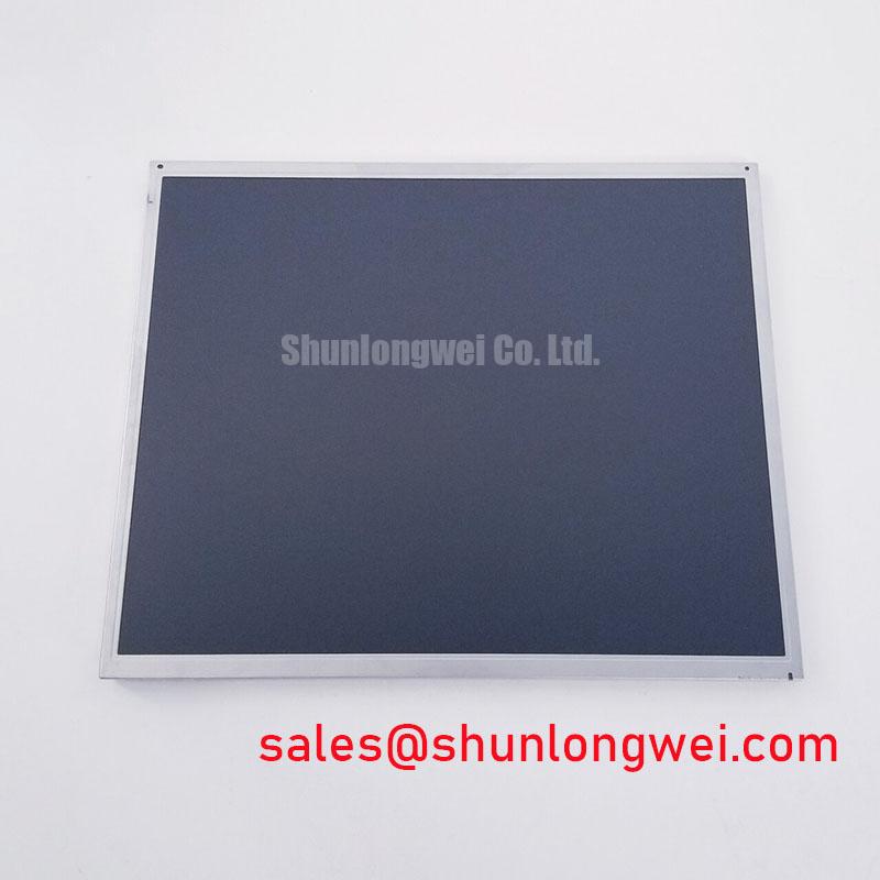
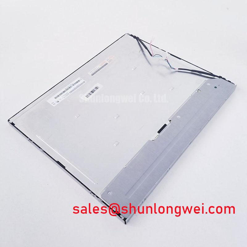
The M170EG01 V9 is an AUO TFT-LCD Display Module listed as an Industrial Grade LCD/HMI Panel. Its available listing classification is Official Factory Spec Verified. For repair work, the original equipment documentation remains the controlling reference for interface assignment, supply requirements, timing, illumination configuration, mechanical dimensions, and environmental limits.
| Item | Listing Information |
|---|---|
| Model | M170EG01 V9 |
| Manufacturer | AUO |
| Product Category | Industrial Grade LCD/HMI Panel |
| Module Format | TFT-LCD Display Module |
| Listing Classification | Official Factory Spec Verified |
Cold-start image behaviour should be assessed at the installed equipment level rather than attributed to the panel without measurement. If a protection terminal or dispatch console shows slow gray transitions, temporary ghosting, or uneven visual settling after energisation, technicians should first compare the symptom with the original panel documentation and a known-good signal path. Ambient temperature, enclosure condensation, controller timing, supply stability, and cable condition can each influence the observed result.
Design Consideration: liquid-crystal display assemblies can show visibly different optical response as ambient conditions change. A cold enclosure should be allowed to stabilise before a permanent panel diagnosis is made. Where a cabinet is exposed to repeated thermal cycling, inspect the display perimeter, front seal interface, frame mounting surfaces, and adjacent enclosure gaskets. A distorted gasket or uneven clamping condition can create mechanical stress that becomes visible as local brightness variation or mura.
The M170EG01 V9 should only be integrated within the temperature and handling limits stated by its applicable AUO documentation and the host equipment documentation. Do not infer a sub-zero operating range, gray-to-gray value, or epoxy-seal qualification from the industrial product category alone. For installations that must remain readable after cold machine starts, the system integrator should validate the complete display assembly under the actual enclosure thermal profile.
For high-noise cabinets, the display data route deserves the same inspection discipline as the panel itself. Engineering Recommendation: preserve controlled differential routing and avoid unnecessary cable stress, sharp folds, or unshielded extensions. The relevant interface impedance, pair-to-pair skew tolerance, and data format must be confirmed against the original panel and controller records before wiring changes are made.
Illumination Drive and Flicker Assessment
Do not assume the illumination technology, dimming method, drive current, ignition requirement, or service-life rating of the M170EG01 V9 without the original panel documentation. These properties are configuration-specific and are not established by the available factory classification. A replacement evaluation should begin by identifying the existing display controller, illumination connector arrangement, and host-board power architecture.
When an installed screen exhibits flicker, intermittent brightness, acoustic noise, or delayed illumination, inspect the full display path rather than isolating the panel as the sole cause. Check connector retention, cable strain relief, display controller output behaviour, power quality, grounding continuity, and enclosure ventilation. Oscilloscope comparison against a known-good signal path can help distinguish between a data-integrity concern, a power-delivery concern, and an illumination-control concern.
Design Consideration: a stable display assembly depends on the interaction of the panel, its illumination subsystem, the controller board, and the cabinet environment. Repairs should preserve the original electrical architecture unless the system documentation explicitly authorises a change. Any conversion between illumination methods, or any alteration to dimming control, requires a complete compatibility review because connector arrangement, electrical limits, thermal loading, and control timing are system-determined.
⚠️ Maintenance Note: During scheduled cabinet maintenance, inspect cooling passages and display-edge gasket condition before resealing the enclosure, because trapped dust and moisture can undermine both thermal stability and long-term visual consistency.
For broader guidance on enclosure exposure, display integration, and industrial HMI service planning, see Industrial Display & HMI Solutions.
Logic Supply Voltage Sequencing and Driver-Interface Protection
The system integrator should verify the required supply voltage from the original panel documentation. The available verified information identifies the M170EG01 V9 as an AUO industrial TFT-LCD module, but it does not establish a specific logic-rail voltage, power-up interval, JEIDA or VESA mapping, connector pinout, or interface timing requirement. These details must match the host controller exactly.
During repair, inspect whether the original failure condition appears only during startup, only after a controller reset, or continuously. Split images, unstable colour rendering, missing sections, and a blank but powered screen can arise from several conditions, including incorrect data mapping, cable damage, poor connector engagement, controller firmware configuration, inadequate power sequencing, or panel damage. Verify each condition through documented measurements and comparison with the known equipment configuration.
Engineering Recommendation: isolate power before disconnecting or reconnecting display cables, then confirm that the cable is fully seated and strain-relieved before energising the console. The display and controller should be treated as one electrical interface. A panel with a similar physical outline is not automatically electrically interchangeable.
For engineers reviewing another AUO industrial panel during a documented compatibility assessment, M185XW01 VE is a separate product reference. Its suitability must be assessed from its own official specifications against the original display’s interface, mounting, optical, and controller requirements; it should not be treated as a direct substitute for the M170EG01 V9.
Signal-Integrity and Differential-Noise Verification in High-Vibration Bays
In high-vibration electrical bays, begin diagnosis with physical evidence: examine cable routing, connector latch integrity, frame retention, chassis grounding points, and any signs of rubbing or repeated flexing. Horizontal noise bands, intermittent pixel disturbance, and image jitter can be related to signal-path interference, grounding discontinuity, mechanical cable movement, controller instability, or external electromagnetic coupling. The observed symptom alone does not identify one cause.
Design Consideration: cable shielding and return-path continuity should be evaluated across the full installation, especially where the display cable passes near switching equipment or high-energy conductors. Shield termination strategy, ferrite selection, cable length, routing separation, connector design, and chassis bonding are determined by the complete equipment architecture. Validation should include live observation of the signal path and image behaviour under representative machine conditions.
Mechanical installation also affects display reliability. Ensure that the front bezel, gasket, and mounting hardware apply pressure evenly according to the host equipment’s documented procedure. Excessive local clamping can create visual non-uniformity, while insufficient retention can allow vibration-related movement. For high-voltage substation protection and SCADA dispatch consoles, engineers should verify enclosure sealing, grounding continuity, display controller compatibility, and service access before returning the terminal to operation.