

Content last revised on October 16, 2026
Flashlight Dark-Shadow Optical Diagnostic to Isolate Logic vs. Backlight Failure Modes
A 45-degree flashlight inspection helps separate a loss of illumination from a loss of image data. With the display powered and a stable test pattern selected, sweep the flashlight across the surface without pressing the panel. A faint menu, text field, or color block visible in the dark area suggests that the LCD is still receiving image information while the illumination path requires attention. A completely inactive image area calls for a different investigation involving the controller, timing path, flexible cable, or panel drive circuitry.
Use a three-pattern bench sequence consisting of primary red, green, and blue screens, then add a white field and a dark field. This makes it easier to distinguish broad illumination non-uniformity from a line defect that follows a particular row or column. A narrow persistent line, repeating vertical artifact, or localized color boundary can be associated with an interconnect or panel-driver issue, but the observation should be compared with a known-good signal path rather than treated as a single-cause diagnosis.
For high-interference control cabinets, the display link should be assessed as a complete differential channel. A design target such as 100 Ω ±10% differential impedance and a skew budget of 50 ps or less may be used only when required by the host interface specification; these are system-level design considerations, not confirmed factory specifications for the G150XTN02-0. Keep the pair geometry continuous through the connector transition, avoid unnecessary stubs, and verify the eye opening at the receiving device with the actual cable and controller installed.
Panel-driver line defects can worsen when the flexible connection is disturbed. Inspect the connector latch, cable seating, and bend path before applying pressure near the glass edge. If a fault changes when the cable is repositioned, document the exact mechanical condition and compare it with a stationary test before approving the panel for service.
Shielded FFC/FPC Flat Flexible Cable Grounding across 360-Degree Connector Shells
Pixel jitter and horizontal noise bands near variable-frequency motor drives should be investigated through the entire cable and grounding path, not through the LCD module alone. A shielded FFC or FPC arrangement should maintain a low-impedance reference around the connector transition where practical, with the cable shield bonded according to the equipment grounding architecture. The correct termination depends on the host controller, enclosure, cable construction, and EMC strategy.
Common-mode suppression can be evaluated when conducted noise is present, but a ferrite component should not be treated as a standard accessory of this AUO panel. Its impedance behavior, current capability, and placement must be selected from measured interference and the complete cable topology. Check the display with the drive idle, accelerating, decelerating, and operating at representative load so that image disturbance can be correlated with switching conditions.
| Evaluation item | G150XTN02-0 product record | System integration action |
|---|---|---|
| Manufacturer | AUO | Match the panel marking and host assembly records |
| Product category | Industrial LCD/HMI panel | Confirm controller, backlight, and bezel compatibility |
| Display construction | TFT-LCD active matrix color display module | Verify interface timing and cable pin assignment from the original system |
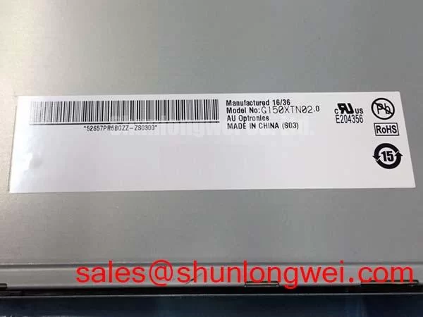
| Specification status | Decoded baseline and standard form factor | Confirm detailed electrical and optical values before replacement |
Ambient-light readability should be evaluated at the intended operator position, including direct sunlight and cabinet reflections. A contrast ratio above 500:1 at 50,000 lux must not be assumed for this model unless it is stated in the applicable panel documentation. Anti-glare behavior is likewise an optical specification to verify, not a default feature to infer from the product category.
AUO’s industrial display information can be reviewed through the AUO Corporation Industrial Display and Embedded Systems resource. The panel technology context may also be compared with general amorphous silicon TFT technology references, while the actual replacement decision remains tied to the original equipment documentation.
Industrial Bezel Mechanical Envelope Tolerances and Mounting Screw Torque Optimization
Mounting stress should be assessed before the replacement panel is clamped into a metal bezel. The chassis opening must support the display without forcing the glass, frame, or connector area into contact with the enclosure. Uneven pressure can produce dark-field non-uniformity, localized optical mura, or an intermittent image path even when the panel operates correctly on a flat bench.
Use a cross-pattern tightening sequence so the bezel load develops evenly. A value such as 0.35 to 0.45 N·m for M3 fasteners is a general design consideration sometimes used during controlled fixture development, not an AUO factory specification for this model. The final torque must follow the enclosure, screw, washer, gasket, and service-manual requirements. Leave the cable exit free from sharp edges and provide a bend path that does not transfer tensile force to the connector latch.
For an HMI installed in a substation protection or SCADA console, compare the replacement panel’s visible area, mounting holes, connector direction, and bezel clearance with the removed assembly before applying sealant or permanent fasteners. A gasket should contact continuously around the intended sealing surface. The enclosure design must also manage dust ingress and condensation without blocking the panel’s required thermal path.
Backlight control requires the host design to match the panel documentation. PWM dimming, if supported by the complete assembly, should be evaluated for visible flicker, audible interaction with the driver, and brightness linearity across the operating range. Values such as 200 Hz to 1 kHz are system-level starting considerations only and must not be presented as confirmed specifications of the G150XTN02-0. When a static SCADA screen remains visible for long periods, rotate status elements or use the controller’s approved display-management function where the system risk assessment permits it.
Maintenance Note: Inspect the cabinet airflow path and gasket compression during scheduled service, and disconnect power before removing or inserting the display cable.
Diffuser Film and Prism Sheet Thermal Buckling Prevention under Continuous Full-Duty Operation
Thermal checks should focus on temperature distribution around the narrow display edges, backlight driver area, and enclosure contact points. Do not press diffuser or prism layers to correct a bright or dark zone; mechanical pressure can create a new optical defect and may permanently alter the panel stack. Instead, record the defect with the panel at operating temperature, then compare it with the display removed from the bezel.
An aluminum heat-spreader rail may be considered where the enclosure creates a localized hot spot, but its size, contact pressure, electrical isolation, and thermal path are determined by the complete assembly. It should not be treated as an internal feature of the G150XTN02-0. The same applies to claims about optical-film composition, yellowing behavior, LED life, L70 performance, or B50 endurance. These values require the applicable AUO panel or backlight specification and should not be substituted with generic LED lifetime assumptions.
For continuous-duty service, log luminance uniformity, backlight drive behavior, cabinet temperature, and visible color change at defined maintenance intervals. A stated curve such as 50,000 hours to 50 percent brightness is not an established product value here. Engineers should use the documented backlight rating, driver current, ambient conditions, and enclosure thermal results when estimating service suitability.
Long-term reliability also depends on power sequencing. The controller should bring the panel supply, logic interface, and backlight enable through the sequence specified for the original assembly, then verify startup for white-screen flashes, delayed image formation, residual image after shutdown, and recovery following a controlled power cycle. For broader enclosure, sealing, optical, and HMI integration guidance, consult Industrial Display and HMI Solutions.