

Content last revised on October 6, 2026
VESA and JEIDA Mapping Checks for Display Signal Integrity
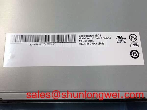
With the equipment isolated from power, check the display connector for poor seating and compare the panel label with the service record before diagnosing the blank screen. The G150XTN02-V0 is an AUO TFT-LCD display module identified for industrial display and HMI evaluation. That identification does not establish the panel’s supply voltage, signal interface, backlight type, optical performance, or mounting dimensions. For a repair, those details must come from the original panel documentation and the host equipment drawings before power is applied.
A powered backlight with a distorted image points the investigation toward the video path, but it does not identify the failed part. Start at the host controller and follow the documented signal path through the cable, connector, and panel input. Check for a partly seated plug, displaced contacts, cable damage near a bend, and changes in the image when the cable is held in its intended position. A stable test pattern is more useful here than a changing machine interface: misplaced colors, repeated columns, and a divided image are easier to distinguish when the source image is known.
Design Consideration: If the original G150XTN02-V0 documentation specifies an LVDS interface, compare the controller’s bit mapping, channel assignment, clocking, and connector pinout with that documentation. VESA and JEIDA describe different arrangements of color data; a mismatch can produce incorrect colors even when a signal is present. A divided or duplicated image can also arise from channel assignment or source configuration. Neither symptom alone proves that the LCD module is defective. Do not apply an LVDS wiring convention to this panel solely because another display in the same equipment family uses it.
Measure the panel input supply at the connector during startup and during the fault, using the limits and sequencing stated in the applicable AUO specification. The system integrator should verify the required supply voltage from the original panel documentation. If the supply falls or rises irregularly, check the upstream regulator and connector before interpreting video waveforms. Where the specified interface is differential, compare the clock and data signals with a known-good path using an appropriate probe setup. Probe loading and a long ground lead can make a usable signal look worse than it is.
Design Consideration: Check transmitter timing at the temperature extremes required by the equipment, because a marginal source or cable can lose timing margin without a visible connector fault. The acceptable clock jitter, data hold time, and interconnect characteristics are determined by the documented panel interface and the host design, not by a universal value assigned to this module. Record the test image, temperature condition, supply behavior, and connector position together; that record makes a repeatable fault more useful than a single photograph of a corrupted screen.
Replacement screening begins with the full mechanical and electrical match, not a similar-looking front surface. The LMS700KF01-001 is a separate display product that may appear in broader repair-material searches; its connector, dimensions, optical requirements, and operating limits would need independent comparison before it could be considered for any equipment. Its listing is not evidence of interchangeability with the G150XTN02-V0.
Tracing Pixel Jitter and Horizontal Lines Near Motor Drives
When horizontal lines appear only while nearby equipment is running, first establish whether the disturbance reaches the image source, the panel supply, or the display cable. Capture the same test pattern with the motor drive stopped and operating, then inspect the controller output and panel-side supply under both conditions. If the controller image is already disturbed, changing the LCD module may leave the fault untouched. If the controller output remains stable, examine the cable route, connector retention, and grounding arrangement without assuming that electromagnetic interference is the only possible cause.
Design Consideration: Keep the display signal return path consistent with the host equipment design when routing a cable near switching power equipment. Shield termination and common-mode suppression can be evaluated when measurements indicate coupled noise, but their placement and effectiveness depend on the actual cable, enclosure, and grounding scheme. A ferrite fitted without those checks is not a guaranteed cure; it may leave a supply disturbance or an intermittent contact unresolved. The equipment designer should confirm the result with the intended cable installation and operating load.
Distinguish moving video noise from a fixed optical defect. A line that changes with the source pattern or equipment state warrants electrical investigation. A mark that stays in the same physical position while the image changes calls for inspection of the display surface, mounting pressure, and optical stack visible to the technician. Clean the viewing surface by the equipment’s approved method before judging contrast or glare. No contrast ratio, sunlight readability rating, or anti-glare treatment is established here for G150XTN02-V0; obtain the applicable optical specification before using any of those properties as an acceptance criterion.
A touch response fault should also be separated from the LCD image fault. A glove-sensitive or wet-touch requirement belongs to the equipment’s touch assembly and controller unless the documented display configuration expressly includes them. Check the touch controller’s diagnostic output and the overlay connection independently of the video test pattern. For a potential railway passenger information terminal or cab display repair, the enclosure, touch arrangement, visibility requirement, and equipment-level qualification all require separate verification; the AUO module designation alone does not establish suitability for that installation.
Backlight Identification and Dark Screen Debugging
Put a known image on the display and check whether faint content remains visible under external light before treating a black screen as a video failure. If image content is present without illumination, trace the documented backlight supply and control path. If no content is visible, continue checking the panel input supply and source signal as well. A dark screen can involve more than one fault, so keep the image-path and illumination-path measurements separate.
The backlight technology of this G150XTN02-V0 configuration is not established by the supplied identification details. Do not select a high-voltage lamp inverter or a constant-current LED driver from a generic LCD repair procedure. Confirm the backlight type, connector assignment, electrical limits, and startup sequence in the original AUO documentation and the equipment schematic, then measure the matching driver at its specified test points.
Field Alert: Disconnect equipment power before reseating the display cable or backlight connector.
Design Consideration: If illumination starts briefly and then stops, compare driver input, enable behavior, and the panel-side connection during the event. A driver protection response, an unstable supply, or a connection problem can present a similar visible result; use the documented circuit behavior to narrow it down. If the complaint is flicker or audible noise during dimming, vary brightness through the equipment’s normal controls while observing the driver and supply waveforms. The acceptable dimming method and operating range must be taken from the specified panel and driver combination, not assumed from another industrial display.
For a washed-out image that is evenly lit, verify the source pattern before adjusting the backlight. Check whether the host is sending the expected grayscale and color values, then compare the result with a known-good signal path where available. Timing-controller and gamma behavior should be evaluated against the module’s documented interface and optical test conditions; an unusual grayscale response is not, by itself, proof that a particular internal board has failed. Consult The Ultimate Guide to Industrial TFT LCD Technology for background when planning display tests across demanding ambient conditions, while retaining the specific AUO limits as the acceptance reference.
Display Edge Support and Thermal Interface Placement
Inspect the installed panel for pressure at its edges before changing a support rail or thermal pad. Uneven brightness, a persistent edge shadow, or an image change after the bezel is refitted can warrant a mechanical check, but the observation does not isolate the panel from the enclosure. Compare the mounting arrangement with the equipment drawing, look for trapped cables and uneven contact, and repeat the image test with the assembly in its normal secured position. Avoid using the visible LCD area as a clamping or heat-transfer surface.
Design Consideration: Any added heat-spreading part should contact only surfaces and locations approved by the panel and equipment documentation. Its material, contact pressure, and path to the enclosure should be chosen to reduce local heating without loading the display assembly or obstructing the cable. Confirm the effect by comparing temperatures and image uniformity under the equipment’s representative operating conditions. An external rail cannot be sized responsibly from the model number alone.
Heat can affect illumination and image appearance, yet the cause of a bright or dark patch still needs measurement. Check whether the patch follows the displayed content, changes with brightness control, or changes as the installed equipment warms. Record the ambient condition, backlight setting, and location of the observation. Do not assign a light-guide material, an LED lifetime, or a brightness-decay curve to G150XTN02-V0 without the corresponding factory specification.
Before closing the enclosure, verify that the panel sits without visible twist, the connector remains fully engaged along its installed cable route, and the test image stays stable after the equipment reaches its normal operating condition. If the display is being evaluated for a cab or passenger information system, compare the documented panel limits with the actual enclosure temperature, viewing position, and maintenance requirements; the final compatibility decision belongs to the equipment integrator.