



Content last revised on September 11, 2026
Industrial Bezel Mechanical Envelope Tolerances and Mounting Screw Torque Control
| Model | G150XG01 V0 |
| Manufacturer | AUO |
| Product Category | Industrial Grade LCD/HMI Panel |
| Display Construction | TFT LCD Active Matrix Color Display Module |
| Specification Status | Official Factory Spec Verified |
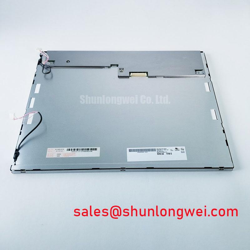
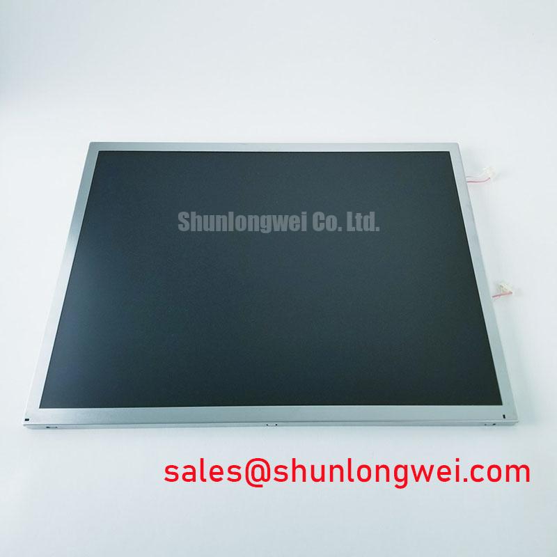
Place the powered off G150XG01 V0 on a clean, grounded inspection surface and inspect the active area, bezel contact points, mounting ears, and connector edge under angled illumination before transferring it into a host chassis. A panel can appear mechanically intact while a bowed mounting frame, trapped cable, uneven bezel pressure, or distorted fastening point produces an optical issue only after the assembly is tightened.
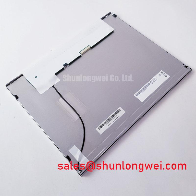
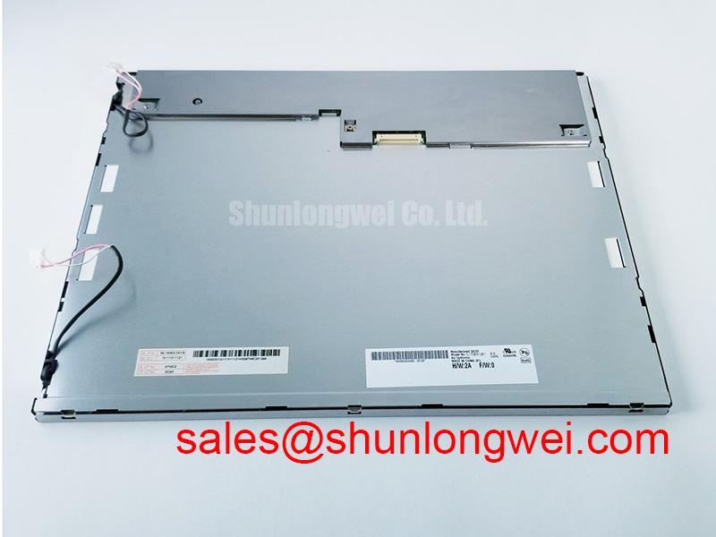
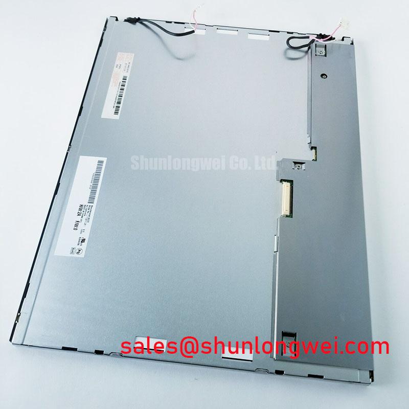
The G150XG01 V0 AUO TFT LCD Active Matrix Color Display Module should be evaluated as a complete mechanical interface rather than as an isolated image surface. During replacement work, compare the original chassis opening, mounting point positions, panel support rails, connector clearance, and rear cover geometry against the removed assembly. Do not rely on a bezel opening alone as evidence of fit. A display can sit within an opening while still receiving concentrated pressure around an edge or corner.
Use a gradual cross pattern when securing the panel so the chassis settles uniformly. The final screw torque is a Design Consideration, determined by the host frame material, fastener type, thread engagement, washer arrangement, and the original equipment manufacturer’s mechanical documentation. Tightening one side fully before the other can introduce local stress that becomes visible as edge shading, pressure marks, or nonuniform dark screen appearance.
⚡ Safety Interlock Note: Disconnect panel power and discharge the host equipment before inserting, removing, or reseating any display cable.
After mechanical installation, run full screen black, white, red, green, and blue image fields while the panel is secured in its normal position. Observe the image from normal viewing distance and from oblique angles. A visual change that appears only after mounting deserves a chassis pressure review before the panel itself is assigned as the source of the defect.
Long duty operation also requires attention to the thermal environment created by the host enclosure. The official factory information supplied for this model confirms its industrial LCD/HMI classification and active matrix color display construction, but it does not establish a specific backlight lifetime, brightness decay curve, or mounting torque value. Any expected service interval must therefore remain a system level evaluation based on the original equipment thermal path, operating schedule, backlight driver behavior, and observed optical stability.
For technicians building a consistent incoming inspection process, The Ultimate Guide to Industrial TFT LCD Technology provides useful background on panel selection factors, display behavior, and integration checks. In practical repair work, retain the results of the first full screen optical test after mounting. That baseline helps separate a preexisting visual characteristic from a change introduced by the enclosure or cable routing.
Thermal Stress Screening During Continuous Full Screen Operation
Run a stable full white test image and inspect the bezel perimeter, rear support surfaces, and enclosure ventilation path for localized heat accumulation that corresponds with visible brightness or color uniformity changes. This method does not diagnose a single cause by itself, but it can reveal whether an image variation follows enclosure temperature, mounting pressure, or the electrical behavior of the host display subsystem.
The G150XG01 V0 is identified by AUO as a TFT LCD active matrix color display module. The factory information provided does not confirm the backlight technology, backlight driving method, optical film composition, brightness rating, color temperature, dimming method, or a rated lifetime figure. These characteristics should not be assumed from panel size, product category, or the appearance of the rear housing.
Thermal management around an industrial panel remains a Design Consideration. System designers generally assess whether narrow panel edges are compressed against a hot chassis rail, whether a rear cover restricts heat escape, and whether nearby power conversion hardware raises the local ambient temperature. The purpose is to avoid persistent temperature gradients that can alter perceived optical uniformity or place added stress on the display assembly.
Check the installed display during a representative operating condition rather than only during a short bench power up. Observe a neutral white field, a midgray field, and a black field after the host system has reached its usual operating state. Compare the result with the panel outside the enclosure when a controlled service procedure permits it. If the image changes with enclosure assembly, inspect mechanical contact and airflow before replacing signal components.
Do not infer a particular optical stack, light guide material, diffuser material, prism sheet construction, or LED performance target for this model without the matching original panel documentation. Such construction details materially affect thermal behavior, but they are not contained in the verified factory facts available here. The system integrator should verify the required supply conditions and backlight requirements from the original panel documentation and the host equipment design.
A practical receiving test records the panel condition at arrival, after initial image stabilization, and after controlled host integration. Note any edge brightening, dark patches, broad luminance variation, flicker, or color shift without assigning a definitive failure mechanism too early. A repeated observation under the same image source and enclosure condition is more useful than a one time visual judgment.
Where the host equipment uses a separate backlight driver or inverter assembly, inspect the driver output behavior with appropriate isolated test equipment and compare it to a known good signal path. Intermittent dimming, audible noise, or unstable brightness can originate in the host power stage, cabling, connector contact, or the display assembly. Isolating the path through controlled substitution and waveform observation avoids treating every dim screen as a panel fault.
Vertical Line Screening and Sub Pixel Column Path Localization
Display solid red, green, and blue fields in sequence, then inspect every vertical line while gently stabilizing the panel cable at the connector without twisting the display assembly. A line that remains unchanged across the primary color fields may indicate a persistent column related image path issue, while a line that changes with cable position or signal movement warrants connector and cable path inspection.
Use a clean digital test pattern source with known image output before drawing conclusions from a vertical hairline defect. Scaling artifacts, timing board behavior, damaged cable conductors, poor connector engagement, and panel level drive faults can all create image symptoms that appear similar at first glance. The service process should therefore progress from source verification to cable inspection, connector engagement, and then panel level assessment.
Inspect the display face under a controlled dark image and use angled external illumination only as a visual aid. A flashlight viewed at an oblique angle can help distinguish a surface scratch, localized pressure mark, or image path line from a broad illumination variation. It is not a substitute for electrical measurement, and it should not be used to make claims about internal driver construction that are not documented for the specific model.
For the G150XG01 V0, the verified product description confirms a TFT LCD active matrix color display module. Interface type, pin assignment, supply voltage, signal voltage, timing format, and connector specification are not included in the official factory parameters supplied for this page. The system integrator should verify the required supply voltage, signal interface, connector pinout, and power sequencing from the original panel documentation before electrical connection.
When a line appears after cable replacement or panel handling, inspect the cable insertion depth and alignment under magnification. Confirm that the latch mechanism is fully engaged where the host connector uses one, that the cable is not folded sharply near the connector, and that no strain from the chassis cover transfers into the mating area. A cable that is visually connected can still be under lateral stress once the cover is fitted.
💡 Bench Tip: Use ESD controls and keep the display cable flat and square to the connector during insertion so that connector engagement can be checked before the retaining feature is closed.
Differential signal routing, trace impedance, and pair to pair timing alignment belong to the host system design review unless the applicable interface documentation establishes those values for the installed panel. These are Design Considerations for maintaining signal integrity in electrically noisy equipment. Measure the actual signal path against a known good reference where possible, especially if a defect appears only when the panel is installed in a particular machine.
Potential use in diagnostic imaging terminals or surgical navigation displays should be treated as a compatibility evaluation example, not a declaration of medical equipment approval. Such systems require the equipment manufacturer to validate the complete display chain, including image processing, enclosure design, electrical safety, cleaning requirements, and any applicable regulatory obligations.
Backlight Power Path Isolation and Driver Assessment
Measure the host display power path with the panel disconnected where the service documentation allows, then compare the connector condition, cable seating, and driver response with the original equipment reference before reconnecting the G150XG01 V0. This isolates host side supply instability from a panel related optical symptom without applying unsupported assumptions about the panel’s internal backlight architecture.
The official factory facts available for this AUO module identify the product as an industrial grade LCD/HMI panel with TFT LCD active matrix color display construction. They do not specify whether this particular revision uses a CCFL or LED backlight, nor do they define ignition voltage, constant current requirements, dimming ratio, backlight connector pinout, or high voltage insulation ratings. Those values must be obtained from the original model specific documentation and the equipment service information.
A dark but still image responsive screen can require investigation of several separate paths. Confirm whether the host system is generating valid image data, whether the display logic supply is present, whether the intended illumination control is active, and whether the cable assembly remains mechanically secure after the enclosure is closed. The symptom may indicate a backlight related condition, but it may also involve the host power circuitry, control signal, wiring, or image source.
Do not connect a generic inverter, LED driver, laboratory supply, or dimming controller solely because it physically mates with a connector. Electrical compatibility depends on the original interface definition, output characteristics, protection behavior, and system power sequence. A replacement display evaluation should preserve the original equipment electrical boundaries until the correct manufacturer documentation has been reviewed.
During controlled troubleshooting, listen for intermittent noise from host power hardware, look for brightness fluctuation while displaying a fixed test pattern, and inspect whether the behavior changes when the enclosure is assembled. Record the sequence of events rather than attributing the observation to one component immediately. This approach is particularly useful when the display operates normally on the bench but becomes unstable after it is returned to the equipment.
Backlight open circuit and short circuit protection functions, if present, belong to the particular driver design and cannot be assigned to the panel from its general TFT LCD classification. Engineers should verify protection behavior through the host driver documentation and safe measurement procedures. If the driver disables output after a fault event, inspect the complete load path, cable condition, connector contacts, and original display requirements before attempting repeated power cycling.
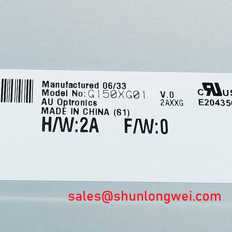
For repair procurement, preserve the full model designation G150XG01 V0 and compare the original assembly’s mechanical fit, display interface, connector arrangement, and optical behavior against the replacement requirements. The panel’s verified AUO identity and TFT LCD active matrix color module construction provide the starting point; correct integration depends on matching the host equipment’s documented electrical and mechanical interface.