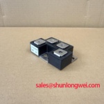
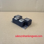
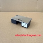
Content last revised on October 1, 2026
PQ160QH06N Thermal-Electrical Optimization: Fuse Total Clearing I2t versus Device Melt Practical Tuning
| Model | Manufacturer | Product category | Package | Rated current | Voltage rating |
|---|---|---|---|---|---|
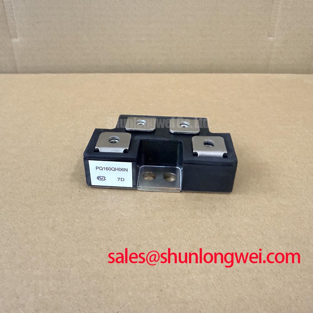
| PQ160QH06N | Nihon Inter (NIEC) | Thyristor/Diode Module | Module | 160.0 A (Official Specification) | Standard Industrial Rating; no numerical value supplied |
Measure the isolated power terminals for an unexpected short before connecting a PQ160QH06N to its buswork. Record each meter lead orientation and compare the cold readings with a known-good unit tested on the same range. A diode-mode reading is useful for checking polarity and consistency, but it does not establish surge withstand capability or prove that the assembly will operate correctly under load.
The 160.0 A rating is an Official Specification for current, not a fuse selection value. For short-circuit coordination, the equipment engineer needs the module’s applicable surge-current and withstand data, the prospective fault current, and the proposed fuse’s total-clearing I2t under matching conditions. Those device limits are not supplied here, so neither a protective fuse rating nor a claim of damage-free fault clearing can be established from the current rating alone. A fuse may protect upstream conductors while still permitting energy beyond a semiconductor’s withstand limit.
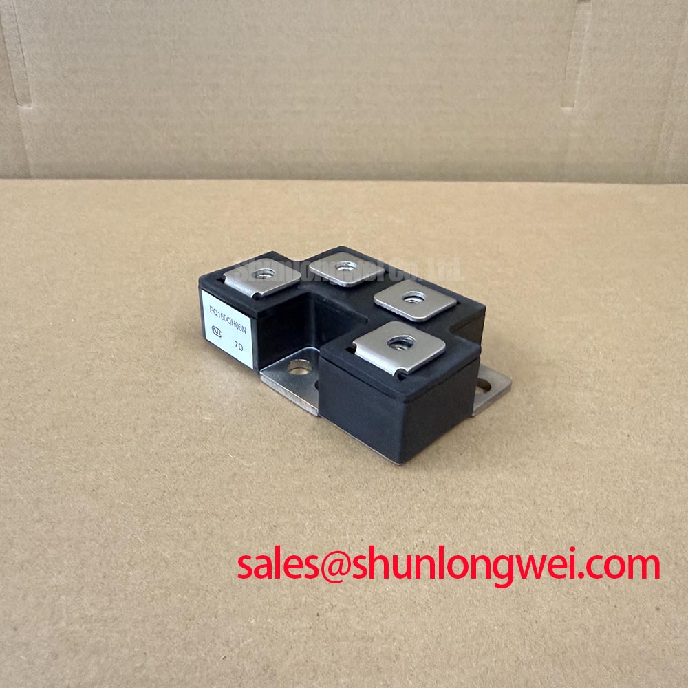
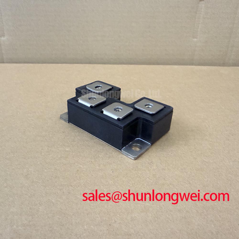
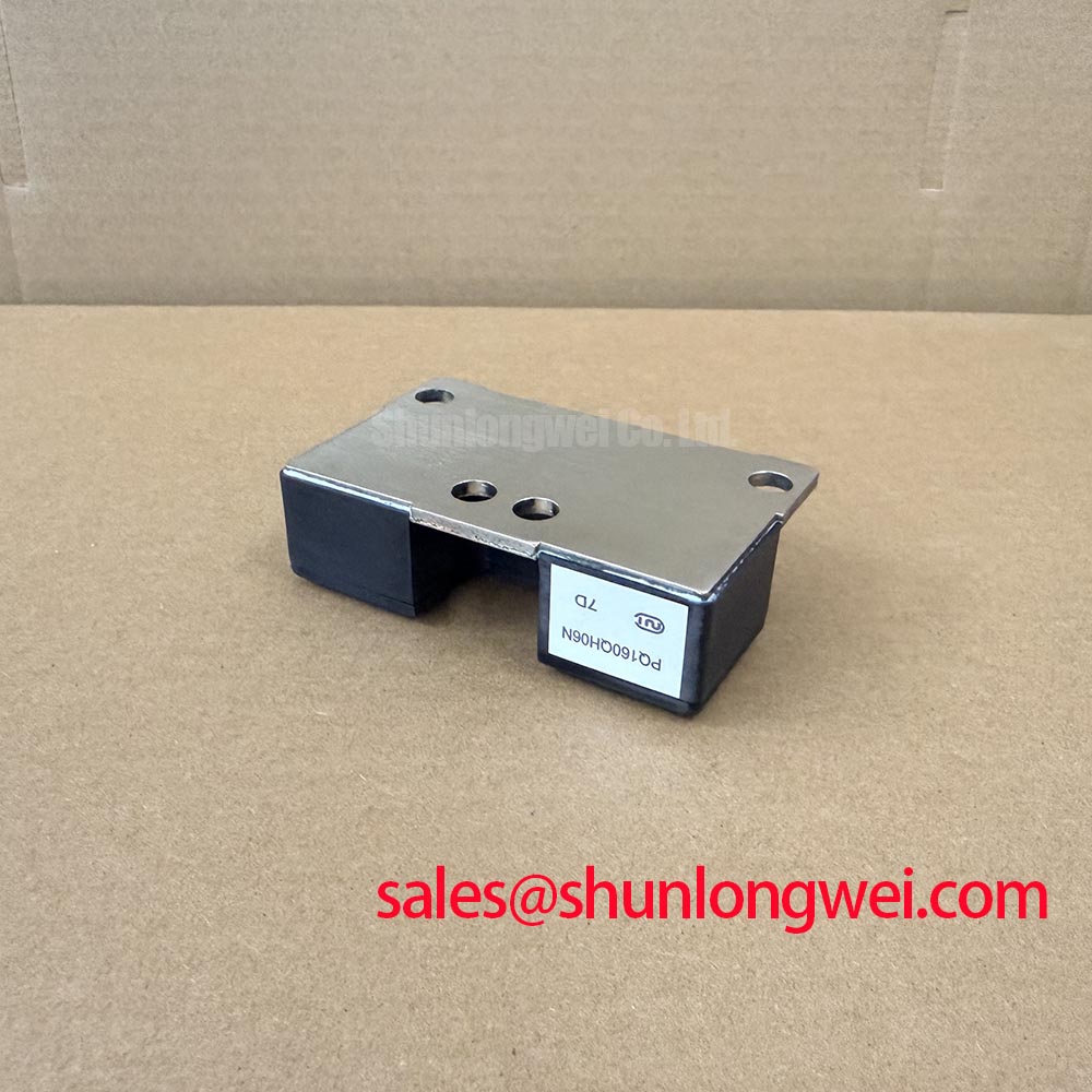
Inspect the mounting face, terminal contact surfaces, and existing hardware before installation. As a Design Consideration, use the fastening sequence and torque specified for the actual module and heatsink assembly; an assumed torque can distort contact pressure. Record the original terminal connections before removal so the replacement can be checked against the equipment schematic rather than terminal position alone.
Preventing Spurious Faults: AC-to-DC Transfer Characteristics across V Guidelines for PQ160QH06N
Trace the AC input and DC output paths on the equipment schematic, then verify the module’s terminal mapping against those paths with power isolated. A rectifier or controlled-conversion stage changes its measured output as operating conditions and, where applicable, firing angle change. That system behavior cannot be derived for PQ160QH06N from its 160.0 A rating: circuit topology, terminal assignment, voltage rating, and firing characteristics must first be established from the matching device documentation.
If the module is being evaluated for a grid-tied static var compensator or thyristor-switched capacitor assembly, identify its position in that specific power circuit before interpreting an AC-to-DC measurement. Such equipment can contain distinct switching and rectification functions; the application name does not establish what this module does inside a particular cabinet. Compare synchronized input voltage, current, and control signals with a known-good channel when diagnosing unexpected conduction or reactive-power behavior. Treat a changed waveform as evidence to investigate, not as proof of a failed module.
An associated rectification stage may be assessed separately from this module. For example, TD285N16KOF is a separate part reference to examine only where the equipment schematic calls for a compatible function. General product information from Shindengen Power Semiconductor Modules & Diodes and the Mitsubishi Electric Diode Modules Lineup can help distinguish module categories; neither source establishes the terminal arrangement or ratings of PQ160QH06N.
PQ160QH06N Circuit Protection & Reliability: Calibrating High-di/dt Gate Firing: Pulse-Train Timing
Probe the gate-drive path against its designated return on the isolated test setup when a controlled branch fails to turn on consistently. Check that the driver reaches the intended terminal pair and that its pulse timing agrees with the equipment control sequence. A pulse visible at the driver board does not by itself confirm that the same waveform reaches the module terminals.
Gate trigger current, gate trigger voltage, permissible gate pulse shape, holding current, and surge limits have not been supplied for PQ160QH06N. Pulse-train strength, rise time, and any back-porch drive therefore cannot be prescribed as part-specific settings. As a Design Consideration, compare the measured gate waveform under representative operating conditions with the confirmed device limits and the equipment’s original drive design. Check for intermittent terminal contact and changes in the gate return path before adjusting the controller.
For incoming inspection, document cold terminal readings and the meter setup alongside the unit identification; repeatability matters more than an unsupported universal diode-drop threshold. 💡 Bench Tip: Discharge the equipment and protect sensitive control connections from electrostatic handling before moving meter leads between terminals. The Field Engineer’s Handbook provides broader test and failure-analysis context for separating a device finding from a driver or connection fault.
Preventing Spurious Faults: Dynamic Voltage Sharing and RC Damping in Guidelines for PQ160QH06N
Capture the voltage across the module during the switching event that produces an unexplained trip, using a measurement setup appropriate to the equipment’s voltage and isolation requirements. Compare the waveform with a known-good branch and the applicable device voltage limit once that limit is established. The supplied “Standard Industrial Rating” description is not a numerical voltage specification and cannot support a claimed peak-voltage margin.
As a Design Consideration, an RC damping network or series reactor should be evaluated against the actual circuit’s stray inductance, switching behavior, and fault response. No snubber resistance, capacitance, reactor size, or dynamic-sharing value can be calculated responsibly from the supplied 160.0 A rating. The system engineer should confirm whether such parts exist in the original circuit, check their connections and condition, and validate any change through measured switching tests.
For a cross-model comparison, PE55GB80 is a separate candidate to assess against the equipment requirements, not an established drop-in replacement. Compare terminal function and layout, voltage and current limits, triggering requirements, mounting interface, and protection coordination before considering interchangeability.