Content last revised on October 4, 2026
Field Diagnostics and Commissioning: Connections, Mounting, and Motor Starting Stress
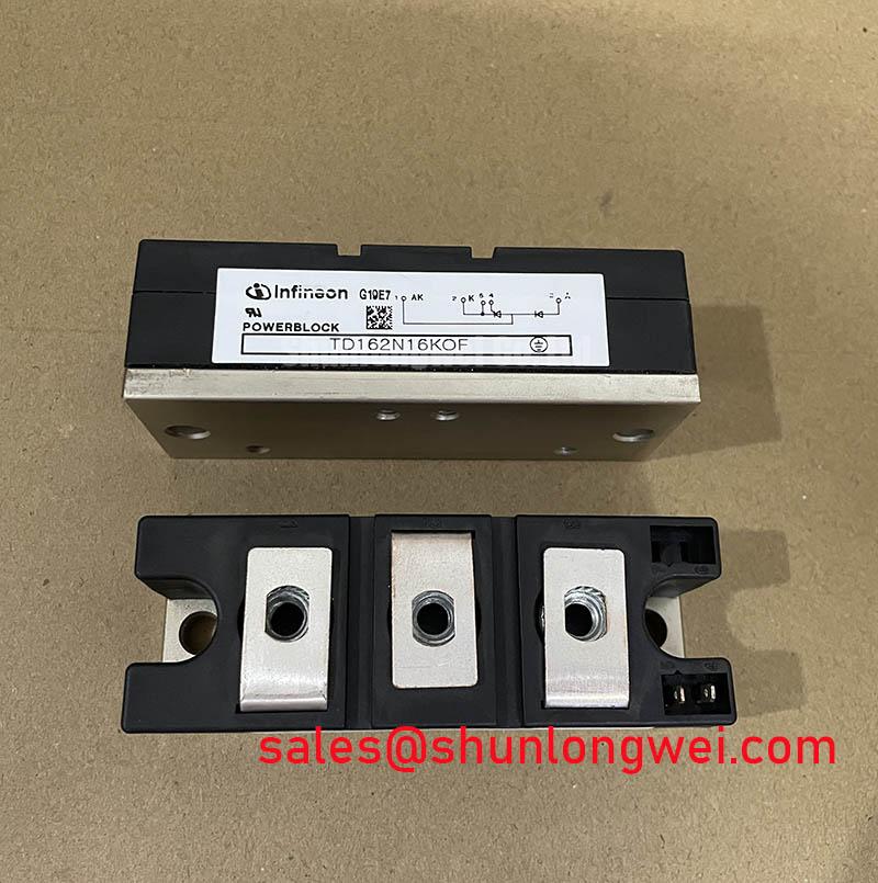
With the motor starter isolated and its DC link discharged, compare the installed module’s terminal connections and mounting footprint with the equipment drawings before considering TD285N16KOF for replacement. Infineon identifies this part as a PowerBlock Module with a 1600 V voltage rating and a 285 A current rating (Official Specification). Those ratings establish an initial electrical screening point; they do not, by themselves, confirm the device’s terminal arrangement, cooling requirements, surge capability, or suitability for a particular starter.
For a high-voltage three-phase motor solid-state soft starter, begin with the installed assembly rather than the desired starting-current target. Record the module marking, terminal positions, busbar orientation, mounting-hole locations, heatsink contact area, and the equipment’s connection diagram. Compare each item with the applicable TD285N16KOF manufacturer drawing before energizing. A matching current rating cannot compensate for a different terminal arrangement or an incompatible mechanical interface.
Phase-angle control can reduce the voltage applied during motor acceleration, but the resulting starting current and shaft torque depend on the motor, driven load, supply impedance, firing sequence, and acceleration settings. Treat any proposed locked-rotor current limit as a system-level performance requirement, not an Official Specification of the module. During commissioning, capture line current in all three phases and observe acceleration under the actual load. Unequal phase currents or an unexpected current rise calls for checks of the firing commands, connections, and motor circuit before changing the ramp settings.
The 285 A rating (Official Specification) should be checked against the manufacturer’s stated rating conditions and the equipment’s measured operating profile. The provided product parameters do not establish a fuse coordination value, mounting torque, or terminal-tightening torque. As a Design Consideration, use the module’s installation documentation and the equipment manufacturer’s service procedure for those values; verify that the selected protective device coordinates with the module’s published surge and energy limits rather than inferring protection from the continuous-current rating.
When assessing the surrounding power path, distinguish the function of each installed device from its package appearance. A module such as TT570N16 can be reviewed in the context of the equipment’s broader power-stage documentation, but its topology and electrical role must be verified from its own specifications before it is treated as a companion device. A schematic showing the rectifier, controlled switching path, bypass contactor, and sensing points is more useful for troubleshooting than a list of similarly rated parts.
Preventing Spurious Faults: Verify the Firing Circuit Before Adjusting Pulse Timing
Identify the actual control terminals from the TD285N16KOF connection diagram before attaching a pulse probe or driver. In a thyristor-based soft starter, reliable triggering depends on the specified gate characteristics and on sufficient drive while the main current establishes conduction. The three confirmed product parameters here do not include gate current, gate pulse width, gate-current rise rate, or a holding-current value. None should be assigned a numerical setting without the applicable manufacturer data and the starter’s firing-board specification.
If a phase intermittently fails to conduct, capture the firing signal at the device terminals while also measuring the relevant phase voltage and current with appropriately rated instruments. Compare the waveform with a known-good phase or a documented service trace. A pulse visible at the control board does not prove that the same waveform reaches the module: connector resistance, wiring changes, or pulse-transformer behavior may alter it. Conversely, an unusual line-current trace does not establish a gate fault on its own; check the power connections and upstream supply before narrowing the diagnosis.
Some controllers use repeated firing pulses across the intended conduction interval. Whether that approach is appropriate for this installation is a system-design question governed by the device’s published gate limits, the driver’s capabilities, and the measured conduction behavior. Avoid transferring gate-drive rules from IGBT modules to a thyristor or diode assembly. Infineon’s EconoDUAL™ 3 material and TRENCHSTOP™ IGBT3 application note address IGBT technologies; they are useful for distinguishing switching-device design principles, not for specifying TD285N16KOF firing pulses.
Benchtop Waveform Tuning: Assess Firing-Angle Changes Against the Actual Load
Before adjusting a soft starter’s firing angle, retain a baseline recording of three-phase line voltage, phase current, firing commands, and acceleration time. Increase the test burden only within the equipment manufacturer’s commissioning procedure. Delaying conduction changes the portion of each AC half-cycle delivered to the motor, so the measured current waveform, input power factor, and heating can change together. The relationship in a real motor starter cannot be reduced to an unloaded AC-to-DC converter transfer curve.
Look at the waveform during the complete start, not only at its highest current sample. A current peak, a prolonged acceleration interval, and unequal phase conduction represent different questions for the control system and thermal design. As a Design Consideration, select the firing schedule to meet the motor-and-load acceleration requirement while checking module current and cooling conditions against the manufacturer’s applicable ratings. The final schedule belongs to the equipment designer or commissioning engineer and requires measurement on the installed system.
The same discipline applies to cross-model evaluation. TD210N12 may appear in a sourcing comparison, but its different model designation is not evidence of interchangeability with TD285N16KOF. Check voltage and current ratings, internal circuit, gate or control characteristics, package drawing, thermal data, terminal layout, and protective-device coordination against the original equipment requirements. Record each mismatch rather than treating a physically mountable module as an electrical substitute.
💡 Pro Tip: Keep the power-path layout consistent with the equipment drawing when replacing the module, then verify switching-related voltage and current peaks under controlled tests before approving a wiring change.
Benchtop Waveform Tuning: Check Half-Cycle Surge and Thermal Recovery
A motor-start waveform can contain brief current excursions that require a different check from continuous-current loading. For TD285N16KOF, the supplied Official Specifications are 1600 V, 285 A, and the PowerBlock Module designation; they do not state a half-cycle surge-current rating or a fuse energy coordination limit. Obtain the applicable manufacturer curves and their initial-temperature conditions before judging whether a recorded transient is acceptable. Do not treat the continuous-current rating as the permissible value for a short surge.
When reviewing a suspected surge event, preserve the current trace, event duration, cooling condition, and timing of subsequent voltage application. Compare that evidence with the manufacturer’s published surge-current and protection data, including the stated conditions for any fuse coordination. Repeated starts also require attention: a waveform that is acceptable from one initial thermal condition cannot automatically be carried over to a hotter module after another start. As a Design Consideration, establish the permitted start sequence from the equipment’s thermal assessment and verify it with temperatures measured at the specified accessible points.
If the starter trips after conduction or near a voltage reversal, examine the phase-current and voltage traces alongside the control commands. The symptom may involve firing timing, commutation conditions, protection settings, or an external connection; a single trace rarely identifies one cause conclusively. For broader context on power-stage design questions, Future of Power Electronics provides related reading, while the acceptance decision for this module remains tied to its own manufacturer specifications and the measured equipment conditions.