


Content last revised on September 20, 2026
MTC300A1600V Operational Boundaries: Evaluating Thermal Avalanche Margins during High Peak Limits
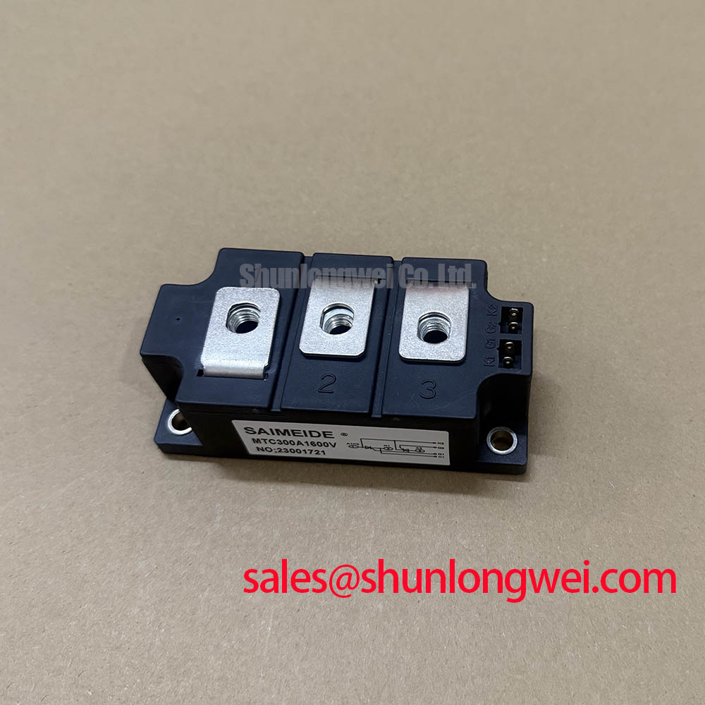
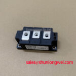
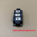
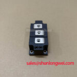
Before installation, verify the nameplate against the replacement record and confirm that the module is specified as MTC300A1600V, manufactured by SanRex (Sansha Electric). Its published electrical limits are a 1600 V repetitive peak reverse voltage, 300 A average on state current at Tc = 85°C, and 471 A RMS on state current. These values define the electrical boundary for assessment in thyristor controlled power assemblies, including high voltage three phase motor solid state soft starters.
| Official Datasheet Specification | Value |
|---|---|
| Repetitive Peak Reverse Voltage, VRRM | 1600 V |
| Average On State Current, IT(AV), at Tc = 85°C | 300 A |
| RMS On State Current, ITRMS | 471 A |
| Threshold Voltage, VT0 | 0.85 V |
| On State Slope Resistance, rT | 1.0 mΩ |
The MTC300A1600V is a thyristor and diode power module, so an inspection should begin with the stated reverse blocking limit rather than with assumptions taken from IGBT switching applications. The official VRRM rating is 1600 V. During maintenance of a three phase motor soft starter, technicians should compare this module rating with the actual phase voltage, transient records where available, the incoming supply condition, and the protection arrangement already approved for the equipment.
The official current reference point is equally important. The module is rated at 300 A IT(AV) with case temperature held at 85°C. This is not a general claim that the module will carry 300 A under every enclosure temperature, heatsink condition, firing angle, motor acceleration profile, or ventilation state. In a phase controlled starter, current waveform shape changes through the ramp. A long acceleration, repeated starts, blocked driven load, weak bypass contactor, or restricted cooling path can raise thermal duty even when the measured line current appears acceptable over a short interval.
The published 471 A ITRMS value provides another official reference for evaluating the heating effect of non sinusoidal conduction. Engineers should use the original equipment manufacturer’s thermal model, phase current waveform, fuse coordination data, and heatsink conditions to establish whether the operating duty remains suitable. No 10 ms surge current rating, fuse I²t value, avalanche capability, junction temperature limit, or mounting torque has been provided in the available official parameters for this listing. These values should therefore be verified from the exact manufacturer documentation and from the original starter design before a protection component or mechanical setting is selected.
In practical servicing, isolate the incoming supply, discharge all energy storage in accordance with the machine procedure, then examine the module terminals and busbar faces for heat discoloration, looseness, contamination, or evidence of uneven clamping. A high resistance terminal joint can create localized heat that is not represented by the semiconductor’s published VT0 and rT values. The 0.85 V threshold voltage and 1.0 mΩ on state slope resistance are official electrical parameters used with the manufacturer’s defined test conditions; they should not be treated as a field pass or fail meter reading.
⚠️ Maintenance Note: Periodically monitor terminal and heatsink contact temperature during comparable load cycles, then correct blocked airflow, degraded thermal interface material, or loose hardware before repeated thermal stress becomes a shutdown event.
Where an existing repair record includes a different current class module, a comparison with the linked FRS200CA100 should remain a documentation exercise rather than an automatic substitution decision. Voltage class, circuit topology, current duty, mechanical outline, gate connection arrangement, thermal path, and the original control board requirements all need confirmation by the system engineer.
MTC300A1600V Circuit Protection & Reliability: Managing Bypass Contactor Duty
In a high voltage three phase motor solid state soft starter, the thyristor power section commonly controls conduction during acceleration and is then bypassed after the motor reaches the intended running condition. The bypass contactor, its auxiliary feedback, and the control sequence deserve the same attention as the MTC300A1600V itself. If bypass fails to close, opens under unsuitable conditions, or provides an incorrect status signal, the semiconductor section can remain exposed to a duty cycle that differs substantially from the equipment’s intended operating sequence.
Design Consideration: phase angle control is used to reduce the mechanical and electrical stress associated with direct motor energization. Locked rotor current in many induction motor systems can be several times the rated motor current, but the actual current reduction achieved by a starter depends on motor characteristics, load inertia, transformer impedance, line conditions, firing control, and acceleration settings. The target current profile and the time allowed at each stage must be established by the system designer. The MTC300A1600V official ratings establish module limits; they do not define a universal motor starting recipe.
During a scheduled inspection, review the controller event log alongside measured phase current and bypass feedback. A repeated fault at the transition from controlled conduction to bypass can involve the contactor path, firing command timing, phase loss sensing, current transformer polarity, gate drive distribution, or a connection issue in the power assembly. It should not be assigned to the module from one symptom alone. A controlled comparison against a known good phase path, performed under the site’s safety procedure, gives more useful evidence than an unloaded continuity test.
Protection coordination must also be retained as an assembly level function. Semiconductor fuses, line fuses, contactors, overload relays, and upstream breakers have different roles. The fuse I²t coordination table applicable to the starter should come from the original equipment documentation and the specified fuse manufacturer data. Since no module I²t or surge specification is included in the official information supplied here, it would be inappropriate to calculate or declare a fuse size for the MTC300A1600V.
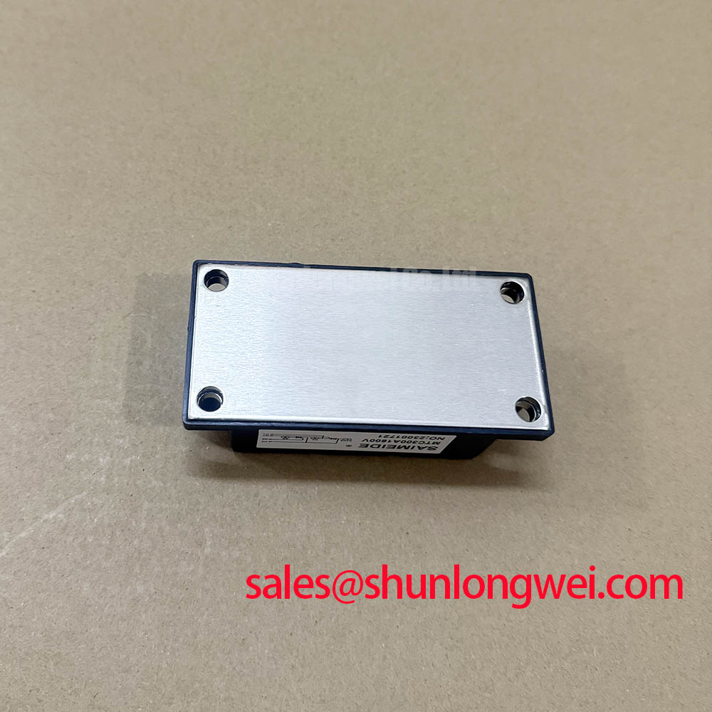
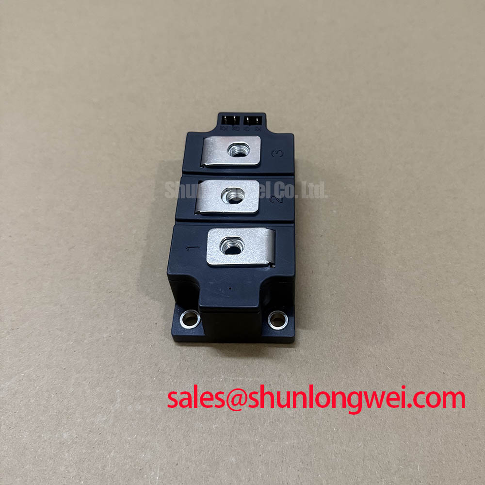
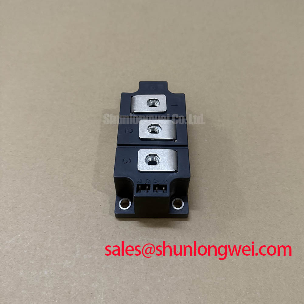
Design Consideration: maintain clean, low resistance power connections and inspect the heatsink surface during planned shutdowns. A thin, uniform thermal interface application and correctly controlled fastener loading are commonly used practices, but the required hardware torque must be taken from the module outline drawing and the equipment manufacturer’s assembly instruction. Do not transfer an M5 torque value or any other generic mounting figure to this module without confirming the terminal and baseplate hardware.
Where the soft starter contains an associated front end or auxiliary power stage, the role of related devices must be traced in the schematic. The linked PK55FG120 can be reviewed as a separate power semiconductor reference, but it is not presented as a prescribed companion device or replacement for any position in an MTC300A1600V circuit.
Preventing Spurious Faults: Limiting Turn-On Current Rise in MTC300A1600V
Unexpected current rise events in thyristor assemblies should be investigated from the complete commutation loop outward. Inspect the physical route from source busbar to module terminal, load connection, return path, snubber components, fuse links, and control reference. Wide spacing, corroded joints, unsupported busbars, and long terminal leads can increase loop inductance and create transient behavior that differs from a clean bench test. Design Consideration: minimize parasitic loop inductance to suppress inductive voltage overshoot during changing current, then verify peak voltage margins in the actual system with suitable isolated measurement methods.
RC snubbers may be fitted across devices or circuit sections to control voltage rate of rise and ringing, but their resistor and capacitor values must be based on the original topology, observed waveform, allowable dissipation, and the applicable component ratings. A generic RC value is not transferable between starters, particularly where supply impedance, cable length, motor size, and bypass configuration differ. When the existing snubber is suspected, check for capacitor degradation, resistor damage, poor soldered or bolted joints, and changes in waveform relative to a verified healthy channel.
Series saturable reactors can also be used in some phase controlled power systems to influence current rise. Their suitability depends on magnetic characteristics, saturation behavior, phase current, fault coordination, and the controller’s firing behavior. The system integrator should verify the original bill of materials and circuit drawing before adding, omitting, or changing any reactor. The MTC300A1600V’s 1600 V VRRM and 300 A IT(AV) at Tc = 85°C remain module level data, not instructions for selecting external suppression components.
Long motor cables require separate attention because transmission line reflections can raise voltage stress at the motor terminals. A reflected wave can approach twice the incident voltage under certain impedance and termination conditions, but the actual result depends on cable type, length, motor winding impedance, source waveform, and installed filtering. This is a motor insulation and system waveform assessment, not a claim about a defined MTC300A1600V capability. Engineers should evaluate line reactors, output filters, cable routing, and measured phase voltage according to the soft starter manufacturer’s guidance.
For equipment that also contains bidirectional DC DC battery charging or discharging hardware, do not combine its thermal cycling analysis with the thyristor starter module assessment without a supported schematic connection. Battery converter switching loops, DC link capacitors, and power cycling profiles are system specific. The useful common maintenance practice is to inspect cooling airflow, condensation exposure, terminal tightness, and thermal interface condition across each power section while keeping each device’s official ratings and topology separate.
Field Diagnostics & Commissioning: Minimizing Commutation Turn-Off Voltage Spikes in MTC300A1600V Topologies
Commissioning should begin with phase by phase verification of supply voltage, motor lead identification, gate command routing, current feedback, bypass status, and protective interlocks. With controlled test conditions approved by the site, capture voltage and current waveforms at meaningful points in the existing circuit. Compare phase symmetry, firing behavior, current sharing, and transfer to bypass against the known good operating sequence. A waveform anomaly may indicate a gate command issue, snubber condition, source imbalance, cable connection problem, load condition, or component degradation; measurement is required before assigning a single cause.
The supplied official parameter set does not state reverse recovery current, reverse recovery time, soft recovery classification, dv/dt rating, di/dt rating, commutation turn off time, or switching loss values for the MTC300A1600V. These characteristics should not be inferred from the product name, voltage class, or ratings of another module. In a thyristor diode topology, commutation behavior depends on the associated diode path, line inductance, load current, gate control timing, and suppression network. When reverse recovery behavior is relevant to a fault investigation, verify it using the exact manufacturer datasheet and a properly rated oscilloscope setup.
Design Consideration: keep the measurement reference loop short and appropriately isolated when examining fast transient behavior, because probe placement can distort the displayed waveform or introduce unsafe ground paths. The objective is to determine whether measured transient voltage stays within the complete system’s validated operating margin, rather than applying an assumed universal limit. For context on airflow modelling, service teams assessing fan changes or heatsink obstruction can consult computational fluid dynamics as a general engineering discipline. Any cooling conclusion still requires confirmation in the actual enclosure.
Humidity control is also part of reliable commissioning. Inspect cabinet seals, heater operation where fitted, drains, filter condition, and evidence of condensation before applying power after a cold shutdown. Moisture can affect terminal insulation surfaces, control connectors, and measurement accuracy. These checks are preventive maintenance practices, not an assertion of a specific insulation rating for the module.
For a broader method covering evidence based testing, connection inspection, and fault isolation, refer to the Field Engineer’s Handbook. Temperature exposure can influence semiconductor wear mechanisms, often discussed through the Arrhenius equation; however, no service life prediction, failure rate, or endurance figure should be assigned to the MTC300A1600V without applicable manufacturer data and validated operating conditions.