


Content last revised on September 22, 2026
Assembly Integrity & Layout Architecture: Implementing Thermal Duty Cycle Management of Bypass Contactor Operation for DKR200AB60
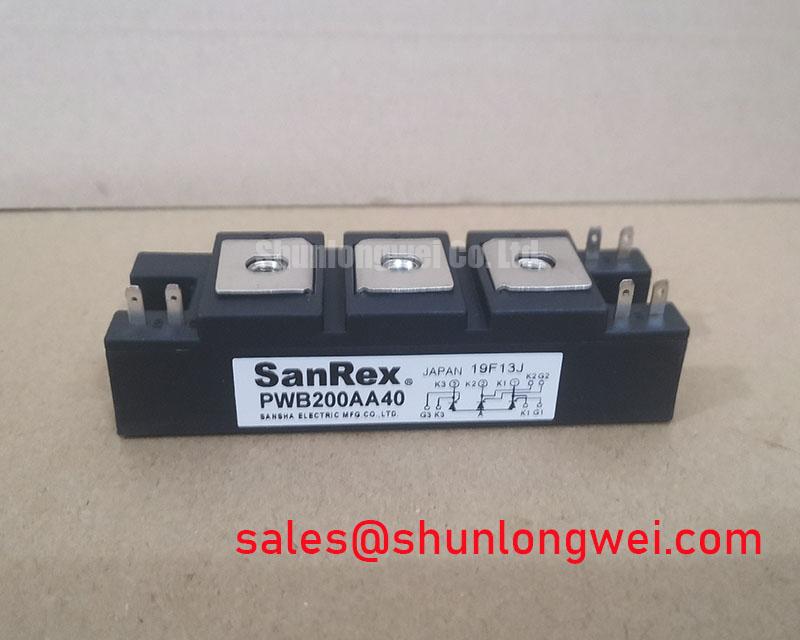
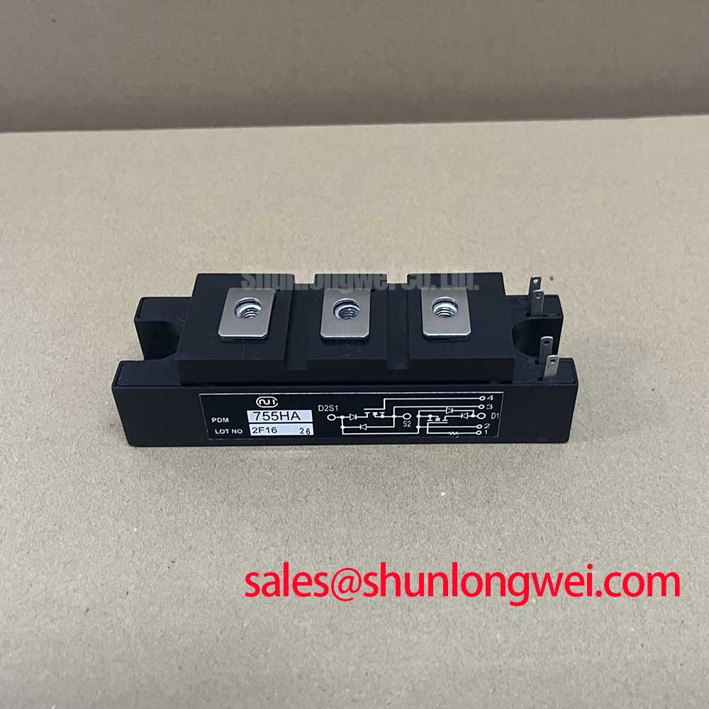
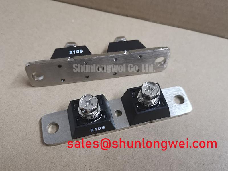
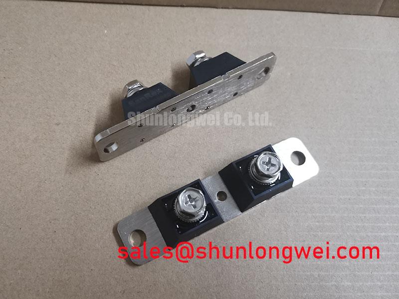
With the isolated DKR200AB60 removed from the power circuit, first compare each accessible power terminal and control terminal position against the original equipment drawing, then record cold diode mode readings in both polarities before applying any firing signal. The DKR200AB60 is a SanRex, also known as Sansha Electric, thyristor/diode module rated at 600 V and 200 A, supplied in a module package as an Official Datasheet Specification. Its suitability in a repair depends on the original circuit topology, terminal mapping, heat sink interface, gate drive arrangement, and protection coordination rather than current rating alone.
For incoming inspection, examine the module body, terminals, mounting surface, and marking area for transport damage, contamination, loose hardware, or evidence of uneven clamping. A diode mode comparison between corresponding terminals can help identify an unexpected low resistance path or an open path when compared with a known good assembly, but a multimeter result does not establish dynamic blocking performance or gate trigger behavior. The system integrator should verify the terminal functions from the original equipment documentation and applicable manufacturer outline information before reconnecting the device.
💡 Bench Tip: Keep the unit electrically isolated during cold testing, use ESD controlled handling around firing connections, and compare polarity readings with a known good module from the same circuit position whenever possible.
| Identification Item | Declared Value | Classification |
|---|---|---|
| Manufacturer | SanRex, Sansha Electric | Official product identification |
| Module voltage rating | 600 V | Official Datasheet Specification |
| Module current rating | 200 A | Official Datasheet Specification |
| Package style | Module | Official Datasheet Specification |
| Terminal map, gate data, I²t withstand, torque, insulation data | Verify from equipment documentation and the applicable manufacturer data | Required integration verification |
Operational Boundaries: Evaluating AC to DC Transfer Characteristics across Voltage Limits
Before testing a phase angle controlled power stage, confirm that the equipment’s applied device voltage, including expected peaks and transients, remains within the module’s declared 600 V rating boundary. This rating must not be interpreted as a universal 600 V AC line-to-line operating limit. The rating is an Official Datasheet Specification for the DKR200AB60, while the voltage appearing across each device position depends on the supply waveform, commutation path, line disturbances, snubber network, motor cable behavior, and control timing. A three phase soft starter is an AC phase control application, not a simple fixed AC to DC converter, yet its firing angle behavior can be examined using the same principle that delayed conduction changes the delivered voltage and shifts the current waveform relative to the supply.
As the firing angle moves from a low delay toward later firing positions, the effective energy delivered to the motor changes and reactive demand can become more significant. This relationship should be assessed with measured voltage and current waveforms from the installed starter, not with a generic calculated curve alone. The motor may not behave as a linear load during acceleration, and a loaded shaft, weak supply, or abnormal cable condition can materially change measured phase current. Engineers should compare all three phase waveforms and should investigate meaningful imbalance rather than assuming a single device is responsible.
Long motor cables can create reflected voltage events at the motor terminals. A reflected wave approaching twice the initial incident step is a transmission line effect that depends on cable construction, length, motor impedance, source impedance, and rise time. It is not a guaranteed module terminal voltage. As a Design Consideration, assess cable routing, output filtering already specified by the starter manufacturer, and measured waveform peaks at relevant locations. The test method should verify that observed peaks remain appropriate for the entire power system, including the DKR200AB60’s 600 V rating.
The physical position of gate and power wiring matters during waveform evaluation. Keep control wiring separated from high current busbars where the original cabinet design intends that separation, maintain the original return paths, and inspect pulse transformer secondary wiring for damaged insulation or loose joints. A ringing waveform may indicate parasitic inductance, poor connection quality, an unsuitable measurement reference, or another system interaction. Use an oscilloscope and a measurement method suitable for the circuit voltage to compare the suspect path against a verified channel or known good unit.
For manufacturer context on power semiconductor module technologies, consult SanRex Sansha Electric Power Semiconductor Modules. The equipment service documentation remains the controlling source for the DKR200AB60 terminal assignment and the permitted operating sequence inside a specific soft starter.
DKR200AB60 Circuit Protection & Reliability: Calibrating the Pulse Transformer Isolated Firing Circuit
A pulse transformer isolated firing circuit should be evaluated at the module terminals and at the controller output before a replacement module is placed under motor load. Confirm that the firing command arrives at the intended gate circuit, that the return connection follows the original routing, and that pulse arrival is consistent across all controlled paths. Gate trigger voltage, trigger current, latching current, holding current, and permissible gate pulse conditions are not included in the supplied official parameter record for the DKR200AB60. Those values must be verified from applicable manufacturer data or the original starter service specification; they must not be substituted with generic thyristor values.
The gate pulse rise time and multipulse firing strategy are properties of the drive system, not confirmed factory characteristics of this module. In practice, a fast and repeatable current transition at the gate is often examined because a weak pulse, excessive loop inductance, or poor secondary connection can impair consistent turn on. The required gate-current rise and pulse conditions must be confirmed against the relevant gate specification and installed pulse transformer capability. They cannot be presented as a DKR200AB60 official rating without direct supporting documentation.
When a controller applies repeated firing pulses around the selected phase angle, check waveform timing across phases and through the expected conduction window. A missing pulse can be caused by controller logic, pulse transformer condition, secondary wiring, connector contact quality, an incorrect reference point, or gate circuit damage. Do not infer a localized gate failure solely from one static test result. Compare pulse shape, polarity, timing, and repetition against the known good signal path using the same probe setup and isolation method.
Protection components surrounding the module also need to remain as designed. Snubber capacitors, resistors, suppression networks, line fuses, current transformers, and control power supplies influence the waveform and fault response seen by the semiconductor. Component substitutions should be checked against the original bill of materials and circuit documentation. If a technician is reviewing related module families while restoring an older controller, the FRS200CA100 is available as a separate product reference, but its use in place of the DKR200AB60 cannot be assumed from nominal current alone.
Gate circuit reliability is best approached through repeatable observations: cold terminal checks before installation, controlled low energy commissioning where permitted by the equipment procedure, and waveform verification before full load operation. This avoids unsupported claims about operating life, failure rates, insulation endurance, EMC compliance, or surge survival that require manufacturer qualification data or a documented system test program.
Benchtop Waveform Tuning: Mitigating Stress via Short Circuit Withstand Limits and Coordinating DKR200AB60 Protection
Short circuit protection review begins with the fact that the DKR200AB60 is officially identified as a 600 V, 200 A thyristor/diode module. The supplied specifications do not include a short circuit withstand duration, surge current curve, I²t capability, avalanche rating, or a specific semiconductor fuse coordination value. It would therefore be unsafe to calculate a clearing energy target, claim zero damage under a dead short condition, or declare a fuse suitable from current rating alone. Fault energy is determined by available supply current, clearing time, fuse characteristics, upstream protection, cable impedance, contactor status, and the device limits documented for the exact module.
For bench review, retain the original high speed fuse designation and inspect the fuse holder, busbar joints, current sensing path, and protective relay inputs. Compare the fuse data sheet’s pre arcing and total clearing I²t values at the anticipated fault current with the protected semiconductor’s authorized withstand information. This is an Engineering Calculation only when both manufacturer data sets and the system fault level are available. If either side is missing, the correct action is to obtain the required documents or use the original qualified protection arrangement rather than estimating a result.
Oscilloscope work should focus on evidence that the protection chain and firing circuit behave consistently. Measure relevant phase voltage and current with properly rated isolated instruments, observe whether gate commands are removed when the starter issues a trip, and verify that bypass contactor state agrees with controller feedback. Any overshoot during interruption should be assessed in the context of probe bandwidth, grounding method, busbar layout, and the system voltage limit. Minimizing loop inductance is a Design Consideration to reduce inductive stress, while final peak margin verification belongs to the system engineer during controlled switching tests.
For background on how resonant and half bridge switching arrangements can change current paths and measurement priorities in appliance power stages, see Resonant Topologies in Home Appliances. That technical context does not transfer module ratings or protection settings to a three phase motor soft starter. The DKR200AB60 installation must remain governed by the original soft starter schematic, verified terminal assignment, declared 600 V and 200 A module ratings, and documented protection coordination.