
Content last revised on September 21, 2026
VVZ24-12IO1 Thermal-Electrical Optimization: Thermal Interface Material Spreading across Practical Tuning
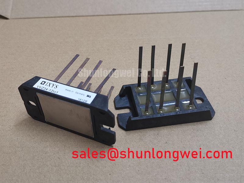
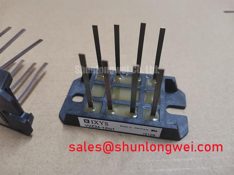
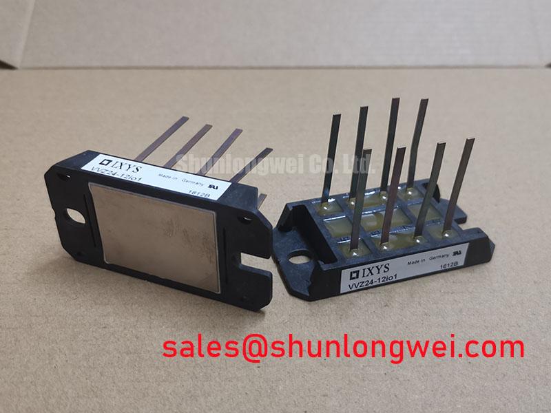
Start a field inspection by isolating the AC and DC circuits, then verify the marking and package before making any electrical measurement. The IXYS VVZ24-12IO1 is a bridge rectifier module specified at 1200.0 V and 29.0 A, housed in a VUO/VUB Case. These are official product specifications supplied for identification and initial system compatibility review.
| Manufacturer | IXYS |
| Part number | VVZ24-12IO1 |
| Product category | Bridge Rectifier Module |
| Rated voltage | 1200.0 V, Official Datasheet Specification |
| Rated current | 29.0 A, Official Datasheet Specification |
| Package | VUO/VUB Case, Official Product Parameter |
For a medium-frequency induction melting or metal hardening power supply, the rectifier is normally evaluated at the front end of the power conversion path. The stated voltage and current values must not be treated as a complete operating prescription. The system engineer still needs to check line conditions, rectification duty, ambient temperature, cooling method, overload profile, fuse coordination, and the applicable IXYS electrical and thermal curves.
Thermal inspection should begin with the copper baseplate and heatsink interface. Remove old compound, check for raised burrs or contamination, and confirm that the mounting surface sits evenly without forcing the module into position. Thermal interface material should be spread as a thin, continuous layer appropriate to the surface finish. The objective is consistent contact pressure and low thermal resistance, not a thick layer that can increase the thermal path.
The available product data identifies the package and electrical ratings but does not provide a mounting torque value or a complete thermal resistance table in the supplied specification set. Use the applicable manufacturer documentation and the mechanical fastener specification for the final installation value. Thermal verification should measure the assembled system under its actual current waveform and cooling condition rather than assigning the 29.0 A rating to every enclosure or duty cycle.
⚠️ Field Alert: Do not tighten the module against an uneven heatsink or connect power cables while the DC link remains energized.
Inspect terminal hardware for discoloration, looseness, damaged threads, and signs of local heating. Cable lugs should sit flat, and the conductor path should not apply side loading to the module terminals. After assembly, record the cold electrical condition and compare the result with a known-good unit or the original circuit documentation. A resistance reading alone is not proof that the rectifier will withstand its rated voltage under operating conditions.
For fuse selection, the required I²t coordination value must come from the applicable IXYS data and the selected fuse manufacturer. No fuse I²t figure is included in the supplied product parameters, so it should not be inferred from the 1200.0 V or 29.0 A ratings. The protection study should account for prospective short-circuit current, fuse clearing behavior, wiring impedance, and the actual rectifier connection.
⚠️ Field Alert: Do not tighten the module against an uneven heatsink or connect power cables while the DC link remains energized.
Preventing Spurious Faults: IEC 61000-4-5 Industrial Surge Immunity: Guidelines for VVZ24-12IO1
An AC input protection review should be performed before commissioning a replacement module. The VVZ24-12IO1 may be evaluated in an industrial rectifier stage, but IEC 61000-4-5 immunity is a system-level performance question. The module itself should not be described as independently passing an equipment surge immunity test.
A design consideration for the AC input is coordinated protection using the appropriate upstream overcurrent device, surge protective components, wiring layout, and enclosure bonding. MOV selection must be based on the real line voltage, temporary overvoltage exposure, surge waveform, energy capability, and coordination with the upstream protective device. The MOV voltage rating should not be chosen from the rectifier’s 1200.0 V rating because those values describe different electrical functions.
RC snubber stages can be considered where the switching network, transformer leakage, wiring inductance, or commutation behavior produces unwanted voltage ringing. Their values are system-dependent and require measurement at the rectifier terminals under the intended load. The practical verification method is to use a suitably rated differential probe and compare the observed peak voltage with the system insulation and semiconductor limits. The final network should be validated for leakage current, dissipation, pulse energy, and temperature rise.
Keep high-current AC conductors physically controlled and minimize the loop area between the rectifier, protection components, and DC-link capacitors. This is a Design Consideration intended to reduce parasitic coupling and overshoot. It is not an official mechanical or electrical limit for the IXYS part. Surge testing should be performed with the complete cabinet configuration, including contactors, filters, transformers, cable lengths, and protective earth connections.
During a fault investigation, inspect the module for cracked housing areas, carbon tracking, terminal heat damage, and discoloration around the heatsink interface. A failed fuse, an abnormal DC-link reading, or a repeated controller trip can have several possible causes. Confirm the upstream protection state, measure the de-energized circuit, and compare each rectifier path with the original schematic before applying power again.
Power semiconductor terminology should also be kept precise. A bridge rectifier module has a different operating role from a power MOSFET. General semiconductor background can be reviewed in Power MOSFET Structure and Operating Principles, but those MOSFET principles should not be used to assign unverified VVZ24-12IO1 switching characteristics.
VVZ24-12IO1 Operational Boundaries: Evaluating Reverse Recovery Charge Temperature Coefficient Limits
When this module is used in a rectifier stage feeding an induction heating converter, reverse recovery behavior should be assessed from the complete commutation circuit. The supplied official parameters confirm 1200.0 V, 29.0 A, and the VUO/VUB Case, but they do not provide reverse recovery charge, reverse recovery time, peak reverse current, or temperature coefficients.
Those values must be taken from the relevant IXYS datasheet curves or application documentation for the exact device revision. They should not be generated from the headline voltage and current ratings. If the rectifier is connected to a high-frequency converter, the system designer should verify commutation voltage, current overlap, transformer behavior, snubber response, and conducted noise with the intended operating temperature.
Temperature changes can alter diode recovery behavior and junction loss, but the direction and magnitude must be supported by device-specific data. A practical test should monitor the rectifier terminal voltage and current during the actual operating sequence. The test engineer can then compare the measured recovery event with the converter’s voltage margin, thermal measurements, and electromagnetic interference limits.
The power loop should be kept compact as a general Design Consideration, especially where fast current changes produce inductive voltage overshoot. The final layout remains system-determined. Validate it with the actual bus capacitors, busbar arrangement, cable routing, gate-drive hardware, and controller timing. The VVZ24-12IO1 should not be treated as a drop-in high-frequency switching device unless the original application documentation confirms the required duty.
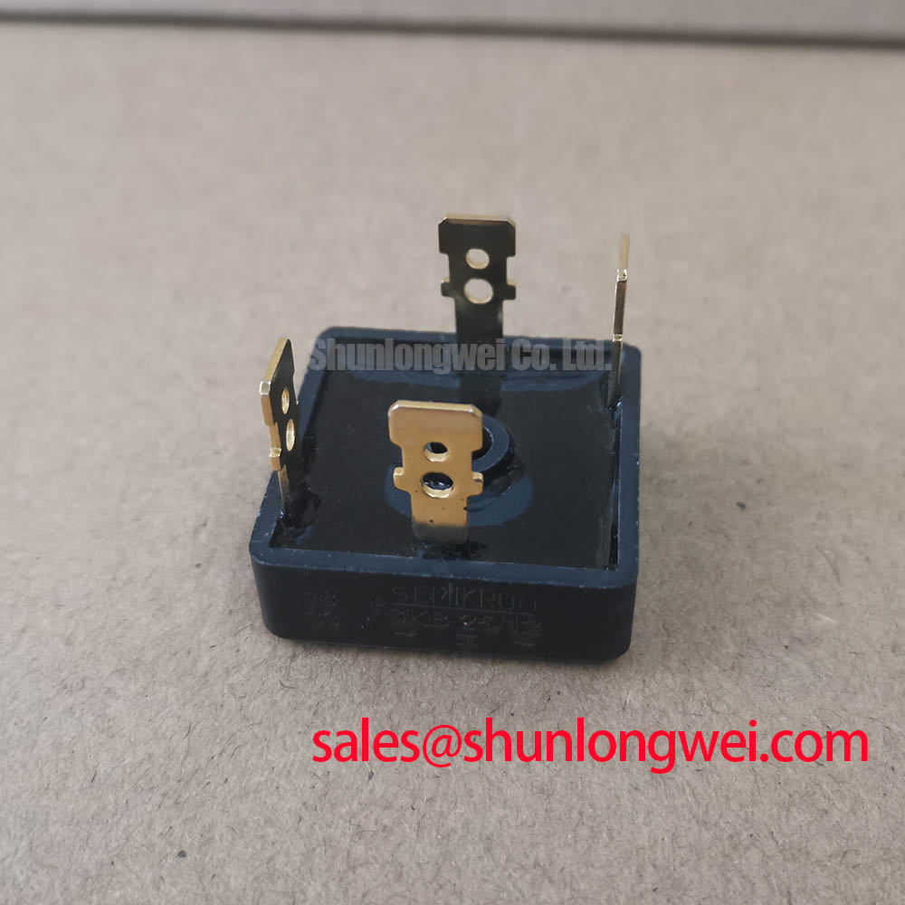
For a replacement assessment, compare terminal arrangement, package geometry, cooling contact, rated voltage, rated current, and protection coordination. The SKD 25/14 can be reviewed as a separate same-family reference model, but electrical interchangeability must be established from the circuit requirements and the respective manufacturer documentation rather than from package resemblance alone.
Field Diagnostics & Commissioning: AC-to-DC Transfer Characteristics in VVZ24-12IO1 Topologies
Commissioning should begin with the original wiring diagram and an isolated module. Confirm the AC input terminals, rectified output path, fuse arrangement, and load connection before energization. With power removed and stored energy discharged, inspect each accessible rectifier path for unexpected conduction, then compare the readings against a known-good module or the manufacturer’s recommended test method. This is a comparative diagnostic check, not a universal pass or fail resistance threshold.
In a controlled AC-to-DC converter, the output waveform changes with the topology, supply waveform, load, commutation overlap, and any controlled firing method placed around the rectifier. The VVZ24-12IO1 product data supplied here does not define a firing-angle transfer curve from 0 degrees to 150 degrees, nor does it specify power factor or reactive power performance. Those characteristics belong to the complete converter and control system.
For a medium-frequency induction melting and hardening furnace, verify the rectifier output with an appropriately rated differential probe and current probe. Record the AC line waveform, DC-link voltage, ripple, current balance, and thermal response during a controlled ramp. If the waveform differs from the reference unit, inspect the control timing, transformer condition, capacitor bank, cable connections, protective components, and measurement setup before assigning the issue to the bridge module.
Any replacement decision should confirm the required voltage and current duty at the installation point. The 1200.0 V and 29.0 A values are official product parameters, not a guarantee of a particular furnace power level, overload duration, cooling arrangement, or converter efficiency. System engineers should verify electrical, thermal, mechanical, and protection margins during commissioning.
For broader context on changing power conversion architectures and evaluation priorities, see Future of Power Electronics. That material provides industry context; the final acceptance criteria for VVZ24-12IO1 must remain tied to the equipment schematic, applicable safety requirements, measured operating conditions, and the relevant IXYS documentation.