Content last revised on November 4, 2026
FF300R12MS4 Infineon 1200V 300A EconoDUAL IGBT Module
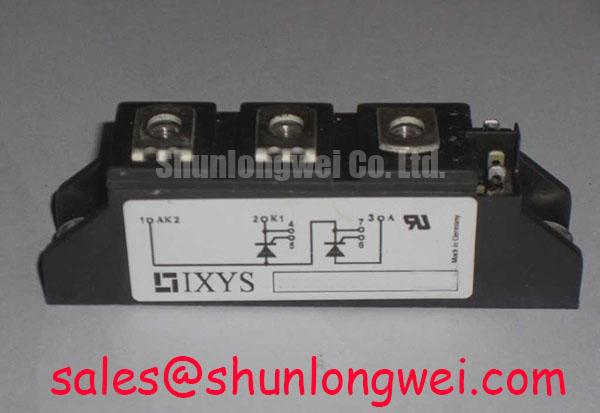
Cold resistance checks, terminal condition, mounting flatness, and gate circuit isolation should be recorded before the replacement module is connected to a traction inverter. The FF300R12MS4 is an Infineon IGBT module with an official rated voltage of 1200 V, an official rated current of 300 A, and an EconoDUAL housing. These values identify the device class, but the usable operating point remains dependent on switching frequency, DC link conditions, cooling, gate drive behavior, protection coordination, and the original converter design.
| Parameter | Value | Status |
|---|---|---|
| Manufacturer | Infineon | Product identification |
| Part number | FF300R12MS4 | Product identification |
| Rated voltage | 1200 V | Official specification |
| Rated current | 300 A | Official specification |
| Package | EconoDUAL | Official physical classification |
- Record cold state resistance across the main terminals and compare the three phase paths for symmetry.
- Inspect the EconoDUAL housing, terminal faces, mounting base, and heatsink contact area before energizing the converter.
- Verify gate driver isolation, gate return routing, interlock timing, and the condition of the driver supply.
- Confirm the original inverter or traction controller documentation before authorizing a replacement in an electric forklift system.
For an industrial forklift or electric material handling vehicle, the replacement decision should include the complete power stage, not only the label on the failed module. Check the original gate driver polarity, switching sequence, current sensor path, DC link layout, braking circuit, and fuse coordination. The same voltage and current markings do not by themselves establish mechanical, electrical, or dynamic interchangeability.
For a neutral same-class comparison, engineers can review FF300R12KE3G alongside the installed device. A comparison should cover terminal arrangement, electrical ratings, switching behavior, thermal interface, gate requirements, and the controller firmware before any substitution is approved.
Field Diagnostics and Commissioning: Planar Symmetrical Busbar Geometry for FF300R12MS4 Topologies
Turn-off overshoot is governed by the interaction between DC link voltage, commutation current, stray inductance, and switching speed. In a practical switching test, the peak collector-emitter voltage rises as the parasitic loop inductance and current slew rate increase. Engineers can use the relationship between the DC link term and the inductive voltage term as an engineering calculation, but the resulting margin must be confirmed with a properly rated differential probe during the actual switching event.
The busbar should present a compact, symmetrical path between the DC link capacitor and the module terminals. Place the positive and negative conductors close together over the full commutation path, reduce unnecessary conductor length, and keep the high-current loop separate from sensitive gate and measurement wiring. The mechanical layout should also preserve the manufacturer’s required creepage and clearance for the actual working voltage, contamination level, enclosure, and applicable safety standard.
A target such as very low loop inductance is a system design objective, not an FF300R12MS4 factory parameter. The designer should derive the acceptable inductance from the DC link voltage, current slew rate, overshoot limit, probe accuracy, and semiconductor voltage margin. A snubber capacitor, damping element, or active clamp can then be evaluated against measured ringing rather than selected from a generic value.
During commissioning, inspect the voltage waveform at the module terminals rather than at a remote point on the bus. A remote probe location can hide the overshoot that reaches the semiconductor. Compare turn-off waveforms for each phase, review ringing frequency and decay, and check whether the abnormal phase follows the module, the busbar position, or the gate driver. That distinction helps separate a layout imbalance from a damaged switching path.
Do not use a normal handheld meter to judge a nanosecond-scale transient. Use an appropriately rated differential probe, a short measurement loop, and a controlled test condition. The test plan should define the DC link state, load current, gate resistance, pulse width, and protection response before the power stage is returned to service.
Field Diagnostics and Commissioning: Thermal Stress Monitoring Across High Current FF300R12MS4 Topologies
At 300 A, the condition of each bolted joint can materially affect local heating. A micro-ohmmeter is useful for comparing the positive, negative, and phase terminal joints under the same test arrangement. The measured value is an engineering diagnostic result, not a published FF300R12MS4 rating. Probe placement, surface condition, clamping force, conductor geometry, and temperature must be controlled so the comparison is meaningful.
Thermal imaging should begin after the converter reaches a stable, representative load. Inspect the main terminals, busbar transitions, fuse holders, cable lugs, and heatsink interface. A concentrated hot area at one terminal can point toward contact resistance, uneven clamping, contamination, conductor strain, or a current imbalance. A broad temperature rise across all phases suggests that the cooling path, operating point, or load profile deserves review.
The heatsink interface must remain flat and clean. Apply the thermal interface material according to the chosen material supplier’s instructions and the module manufacturer’s mechanical requirements. The mounting method should distribute pressure evenly without distorting the housing. Confirm the appropriate fastener procedure from the assembly documentation instead of transferring a torque value from another package.
Fast semiconductor fuse coordination requires an I2t comparison with the module’s permitted short-circuit and surge conditions. The fuse must clear the fault within the energy and time window supported by the complete power stage. This is a coordination exercise involving the fuse curve, wiring impedance, DC link capacitance, gate shutdown behavior, and protection detection delay. A fuse selected only by its continuous current rating may not provide suitable sub-cycle protection.
Review the event recorder after any fuse operation. Capture gate driver fault status, DC link voltage, phase current, and the timing between fault detection and gate blocking. A short-circuit event can also stress the driver isolation barrier and auxiliary supply, so replacing the power module without checking those circuits can allow a repeat failure.
Field Alert: Isolate and discharge the DC link before removing terminals or gate cables, then verify the absence of hazardous voltage with an approved measurement procedure.
Transient Dynamics and Electrical Design: Diode Softness Optimization via System Verification
The antiparallel diode affects commutation behavior when the opposite IGBT turns on. Reverse recovery current, current slew rate, device temperature, busbar inductance, and gate resistance interact during this interval. A hard recovery event can increase voltage ringing and radiated noise, while excessive damping can increase switching loss and thermal load. The appropriate balance must be established from measured waveforms and loss calculations for the actual converter.
During a double-pulse or equivalent controlled test, observe the diode recovery current with a bandwidth and sensor arrangement suitable for the event. Look for the relationship between reverse recovery current, collector-emitter overshoot, gate voltage disturbance, and the current in adjacent phases. A waveform that appears acceptable at light load can become unsuitable at the traction inverter’s higher current operating point.
Turn-on gate resistance can be evaluated as a tuning variable when the measured recovery event creates excessive ringing or electromagnetic interference. The starting value should come from the original driver design and the module documentation, then be adjusted only after checking switching loss, gate voltage stability, dead time, and thermal behavior. It is not appropriate to assign a universal resistor value to every installation.
RC snubbers should be connected with the shortest practical loop and evaluated for pulse energy, resistor heating, capacitor voltage rating, and interaction with the DC link capacitor. Snubber selection is a system calculation based on measured ringing energy and frequency. The installed network should be validated at the intended current, temperature, and switching condition.
When the original application uses a bidirectional DC to DC battery converter, examine both charge and discharge directions. The semiconductor loss pattern can change with current direction, regenerative braking, battery voltage, and control mode. Thermal cycling is influenced by the complete heatsink, power profile, switching strategy, and enclosure temperature. The FF300R12MS4 rating should therefore be used as an input to the thermal design rather than treated as a direct guarantee of a particular duty cycle.
For topology context, the engineering guide Resonant Topologies in Home Appliances explains how switching topology changes current commutation and device stress. The principles are transferable to power conversion analysis, but the actual traction inverter remains responsible for its own timing, current, and thermal validation.
Preventing Spurious Faults: Common Mode Transient Immunity in Harsh Industrial Gate Drive Systems
False gate commands during fast common mode movement usually require inspection of the complete isolated driver path. Check the isolation barrier, gate return, driver supply decoupling, signal reference, Miller control arrangement, and controller interlock. A power module does not independently establish the CMTI performance or reinforced isolation rating of the assembled gate drive.
The isolation design should be evaluated against the required working voltage, transient voltage, pollution environment, creepage, clearance, and safety standard. Do not infer a greater than 5 kV isolation capability or a CMTI above 100 kV per microsecond from the module’s 1200 V rating. Those are system or driver characteristics that require documentation and test evidence for the selected isolator, layout, and assembly.
Use an isolated oscilloscope arrangement to observe the command signal, gate-emitter voltage, collector-emitter voltage, and driver supply during the fastest switching transition. A narrow unwanted gate pulse may be caused by capacitive coupling, insufficient return control, driver supply bounce, probe reference error, or timing interaction between upper and lower devices. Check the waveform against a known-good phase and vary only one controlled condition at a time.
Dead time must prevent cross conduction while preserving the required output voltage and current control. The correct interval is determined by device switching delay, temperature, gate resistance, driver propagation mismatch, diode recovery, and the controller’s timing resolution. Excessive dead time can increase diode conduction and recovery stress, while insufficient dead time can create shoot-through risk.
Gate wiring should be short, clearly referenced, and physically separated from high-current commutation paths. The driver should shut down predictably during overcurrent, undervoltage, desaturation, or controller fault conditions. Verify the fault latch, reset behavior, and restart sequence with the DC link controlled at a safe test condition.
For a forklift traction repair, final commissioning should include unloaded rotation, controlled current increase, regenerative operation where applicable, thermal observation, and review of gate waveforms at the intended switching condition. The FF300R12MS4 provides the identified 1200 V, 300 A device class in an EconoDUAL package; safe integration depends on the verified electrical, thermal, mechanical, and protection design surrounding it.