

Content last revised on September 10, 2026
Field Diagnostics & Commissioning: Phase Controlled Rectification and Firing Angle Checks for PGH50N16 Topologies
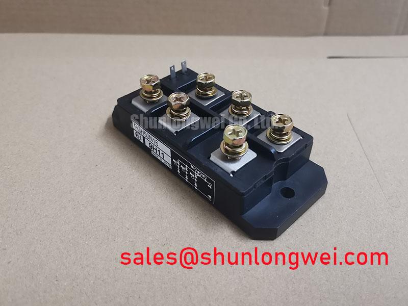
Before connecting the module to a live cabinet, isolate it from the power circuit and compare each accessible terminal pair with the original equipment schematic using a multimeter diode function. The PGH50N16 is specified as a 1600V, 50A Isolated Power Module from Nihon Inter, also identified as NIEC. These are the confirmed official datasheet specifications available for this product page. Terminal names, internal circuit arrangement, gate characteristics, isolation test conditions, thermal resistance, surge rating, fuse coordination values, and mounting torque are not established by the supplied official parameter set and should be verified against the original equipment documentation before installation.
For phase controlled rectifier maintenance, first confirm that the incoming AC phase sequence, firing board reference, gate pulse routing, and DC output polarity correspond to the original cabinet wiring. A phase control circuit changes its average DC output as its firing angle is delayed through the AC waveform. During commissioning, an Engineering Recommendation is to begin with the existing firing board settings and confirm pulse timing against the known controller sequence rather than imposing a new angle value. A firing angle sweep from zero through delayed conduction positions can reveal missing pulses, phase imbalance, unstable synchronization, or insufficient load current for latching, but the usable operating range remains system determined.
As firing delay increases, the rectifier transfers less active power to the DC link while reactive current demand can increase. This relationship is especially relevant when evaluating a medium frequency induction melting or hardening furnace power supply, where a distorted incoming waveform may be related to the firing controller, supply impedance, transformer condition, current feedback path, or downstream inverter load. It should not be assigned to the PGH50N16 alone without waveform evidence.
Use an isolated oscilloscope measurement method appropriate for the equipment voltage category to compare phase voltage, synchronization reference, firing pulse timing, and rectified output. If one phase produces a different conduction interval, inspect the firing transformer or pulse distribution circuit, the associated wiring, and the terminal continuity before replacing the power module. Where isolated phase current feedback is part of the diagnostic chain, the principles behind GMR and TMR current sensing can help explain why sensor offset, magnetic placement, or signal conditioning should be checked alongside the power stage.
| Verification Item | Available Status | Workshop Action |
|---|---|---|
| Blocking voltage | Official Datasheet Specification | Confirm that the circuit voltage and measured transient peaks remain suitable for the 1600V module rating. |
| Current rating | Official Datasheet Specification | Confirm that the rated current is evaluated against the 50A rating and actual thermal conditions. |
| Package type | Official Datasheet Specification | Confirm heatsink interface, terminal layout, and clearances for the isolated power module enclosure. |
| Fuse I²t coordination | Not provided in the available parameter set | Use the original fuse documentation and protection study. Do not infer coordination from the 50A rating alone. |
| Mounting torque | Not provided in the available parameter set | Follow the module drawing or original equipment service documentation. |
💡 Bench Tip: Keep the gate and power terminals discharged and use static safe handling while recording cold state readings from the removed module and, where available, a known good assembly.
When an equipment repair requires evaluation of another module, terminal arrangement, internal topology, voltage class, current class, thermal interface, and protection compatibility should all be checked independently. The linked DDB6U180N16RRP_B37 can be reviewed as a separate power module reference, but it must not be treated as a direct replacement unless the complete electrical and mechanical comparison is documented by the system engineer.
Transient Dynamics & Electrical Design: RC Snubber Network Review for PGH50N16
An RC snubber inspection starts at the existing wiring rather than at a calculated component value. With the PGH50N16 disconnected and the capacitor bank safely discharged, inspect the snubber capacitor condition, resistor continuity, connection tightness, and routing between the controlled power terminals. The purpose of a snubber is to manage transient voltage behavior across a switching or phase controlled device when circuit inductance and interrupted current create overshoot. This is a Design Consideration, not an Official Datasheet Specification for the PGH50N16.
The supplied product information confirms a 1600V voltage rating, but it does not provide an allowable repetitive voltage rise rate, nonrepetitive surge figure, recommended RC values, internal junction behavior, or maximum current rise rate. For that reason, capacitor and resistor selection must be derived from the measured circuit waveform, the existing equipment design, the load inductance, commutation path, and the original protection documentation. An altered snubber can reduce one form of stress while increasing dissipation or affecting commutation behavior elsewhere in the system.
When reviewing a furnace rectifier, monitor the voltage across the power stage with suitable isolated instrumentation and compare captured waveforms before and after service work. A ringing edge may indicate loop inductance, a degraded snubber component, loose buswork, an issue in the commutation network, or a measurement setup problem. The correct response is to verify the entire current path and peak voltage margin against the DC link during switching tests. It is not appropriate to prescribe a universal RC value for this module without the original circuit conditions.
Series saturable reactors, where included by the equipment manufacturer, are also system components rather than accessories that can be selected only from the module current rating. Their behavior depends on the intended current waveform, core condition, winding integrity, and the protection strategy. Inspect for discoloration, loose terminations, cracked insulation, and evidence of mechanical movement. If a reactor has been replaced, confirm its characteristics against the original service bill of materials before energizing the cabinet.
Phase controlled furnace systems often include an upstream rectification or auxiliary power section. A related device such as PK55FG120 may be reviewed when mapping associated rectifier positions or complementary power circuits, although its electrical function and suitability must be verified from the actual schematic. Separating power stage faults from control supply faults prevents a repair effort from attributing every waveform abnormality to the PGH50N16.
Current measurement should also be treated as part of transient diagnosis. Isolated feedback circuits can use oversampled conversion methods, and the operating principle of delta sigma modulation provides useful context when checking whether apparent current instability originates in the sensor path, isolation interface, controller filtering, or the power circuit itself. Compare the displayed current with a suitably rated independent measurement before changing protection thresholds.
Preventing Spurious Faults: Thermal Interface Material Spreading Guidelines for PGH50N16
Remove the PGH50N16 only after verifying that stored energy has been discharged and that every power and control lead is identified. The confirmed housing classification is an Isolated Power Module, which indicates an isolated package arrangement but does not establish a complete thermal interface specification, dielectric test value, baseplate material, or permitted mounting force. These details should be taken from the original NIEC documentation or the host equipment manufacturer’s service instructions.
Before mounting, clean the mating heatsink surface and inspect it for burrs, corrosion, trapped debris, flatness issues, or residue that could prevent full contact. A thin, uniform thermal interface material layer is a general Design Consideration because excessive material can increase thermal resistance while insufficient coverage can leave local contact voids. The correct amount, compound type, and installation method remain system determined. Do not assume that a paste thickness or torque value used by another module family applies to PGH50N16.
Fasteners should be tightened using the sequence and torque specified for the actual module drawing and heatsink hardware. Alternating tightening locations can help distribute clamping load during assembly, but this is an Engineering Recommendation rather than a factory torque requirement. Check that the module sits flat before final tightening and that busbars or cables do not impose twisting force on the terminals. Mechanical stress can affect electrical connections, thermal transfer, and clearance distances.
After installation, inspect terminal alignment and confirm that the connected conductors do not pull the package away from the heatsink. In a medium frequency induction heating supply, thermal cycling can reveal a mounting inconsistency through recurring protection trips, uneven temperature indication, or changes in output stability. These signs can also arise from airflow, coolant circulation, current imbalance, firing timing, sensor drift, or load variation. A controlled inspection should therefore include temperature comparison across the heatsink, electrical waveform review, and verification of the cooling system condition.
No official junction to case thermal resistance value is available in the supplied PGH50N16 data. Any thermal calculation based on unverified resistance values would be an assumption, so temperature margin should be evaluated using the original thermal design data and measured operation under controlled load conditions. Engineers assessing stress limits and maintenance practices can also consult Future of Power Electronics for broader repair and test context, while retaining the equipment schematic and manufacturer documentation as the controlling references for this module.
Benchtop Waveform Tuning: Gate Trigger Current Dynamics on PGH50N16
Gate trigger troubleshooting should begin by observing the existing firing pulse at the module connector with the power circuit safely isolated or under an approved reduced energy test condition. Confirm pulse presence, polarity, phase relationship, repetition pattern, and consistency across equivalent channels. The available PGH50N16 data does not state gate trigger current, gate trigger voltage, holding current, latching current, gate power limit, or permitted gate current rise rate. Those values must not be inferred from the module’s 1600V and 50A power ratings.
A gate pulse that appears correct at the control board may not arrive unchanged at the module due to wiring resistance, firing transformer condition, connector contamination, reference errors, or damage in an isolation stage. Compare the signal at the source and the module end where safe access is available. If pulse amplitude or shape differs between phases, inspect the complete drive channel before condemning the power device. A missing or unstable firing event may also be related to synchronization loss, controller interlock logic, gate return routing, or a protection signal that is intentionally suppressing operation.
Multi pulse firing methods are sometimes used in phase controlled systems to improve trigger confidence across changing load conditions. This is a system level Design Consideration and cannot be prescribed for PGH50N16 without official gate specifications and the original control design. Any change to pulse width, repetition, source impedance, or firing timing should be validated against measured anode current, device voltage, transformer heating, and the behavior of the full protection chain. A stronger gate signal is not automatically a safer one when the applicable gate limits are unknown.
For controlled rectification in induction melting and hardening furnace power supplies, compare firing timing with output current and DC link behavior as load demand changes. An apparent device fault can be caused by a gate drive path that does not provide consistent triggering, while an apparent gate problem can be caused by a load condition that prevents normal current establishment. Keep the diagnosis evidence based: record the waveform, identify the measurement point, compare it with the original circuit expectation, and verify the terminal map before selecting a replacement module.
The PGH50N16 should be specified in service documentation as a Nihon Inter NIEC 1600V, 50A Isolated Power Module. This concise identification preserves the confirmed product facts while leaving topology, terminal allocation, gate requirements, fuse coordination, snubber values, thermal limits, and mounting requirements under control of the original equipment documentation.