
Content last revised on September 15, 2026
Transient Dynamics and Electrical Design for a 10 ms Half-Cycle Surge
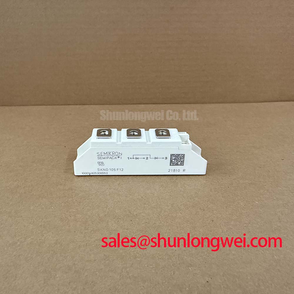
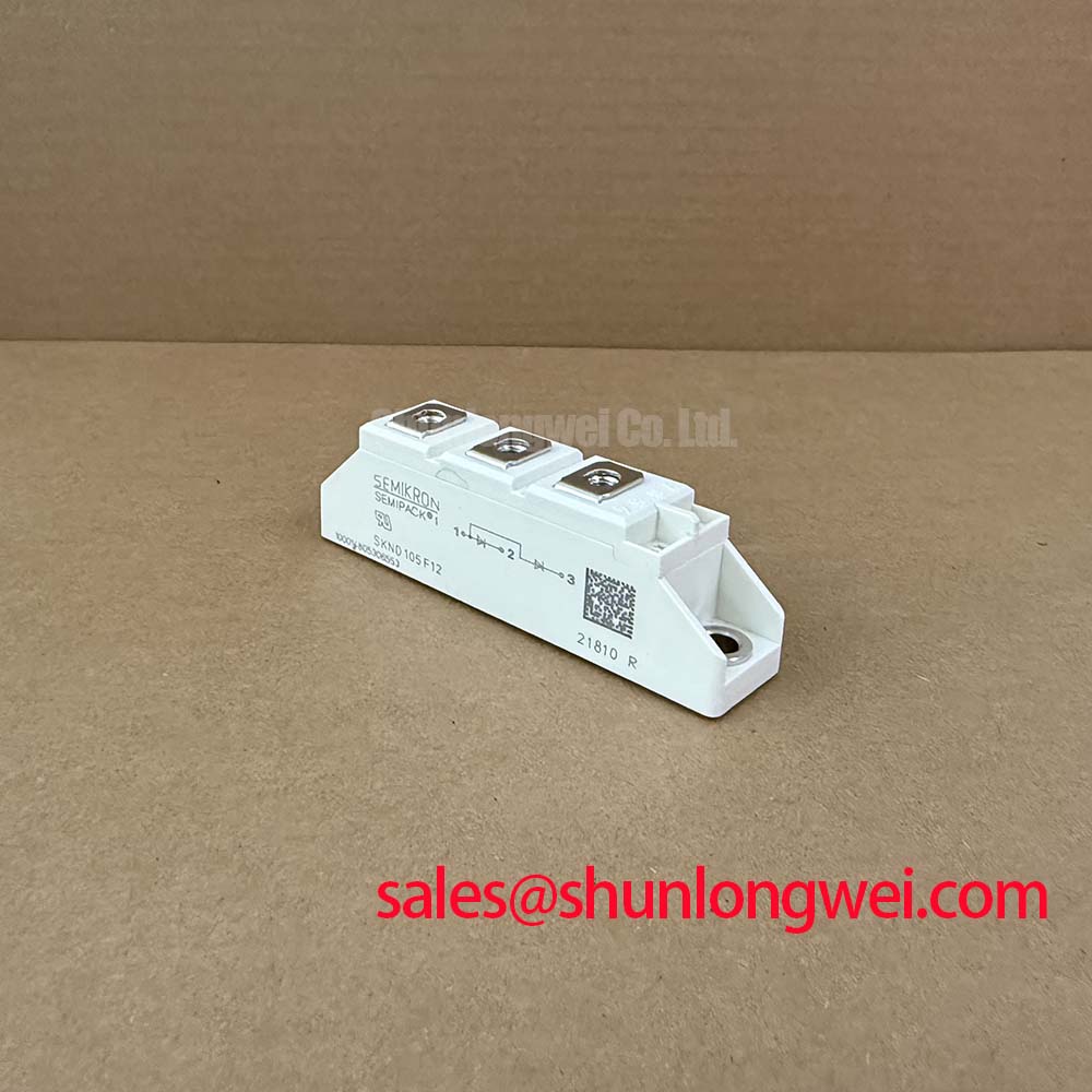
The official datasheet specification lists a continuous forward current of 105 A under sinusoidal 180° operation with case temperature at 83 °C. Its maximum RMS forward current is 200 A for continuous operation. During a non-repetitive fault event, the specified surge forward current is 2500 A for 10 ms at a junction temperature of 25 °C, with an i²t value of 31,250 A²s under the stated 8.3 to 10 ms test condition.
These figures are device ratings, not permission to operate a bridge continuously at surge conditions. When coordinating semiconductor fuses, the protection study should compare the fuse clearing characteristic with the diode’s specified i²t value, prospective short-circuit current, DC-link capacitance, and the complete bridge topology. The system engineer should also confirm junction temperature behavior before reverse voltage is reapplied.
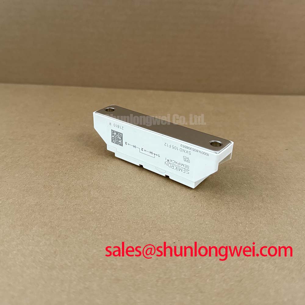
The maximum peak forward voltage is 2.05 V at 300 A and 25 °C. This value should be included when estimating rectifier conduction loss and checking heat-sink capacity. The specified junction-to-case thermal resistance is 0.24 K/W per diode and 0.12 K/W per module. Actual thermal performance remains dependent on mounting flatness, interface material, cooling airflow, and the assembled heat path.
Circuit Protection and Reliability in High-Current Rectifier Assemblies
SKND105F12 is a diode, so gate firing pulse rise time, back-porch holding current, multi-pulse gate firing, and gate hotspot prevention are not applicable device functions. Those requirements belong to a controlled thyristor or similar gated semiconductor elsewhere in a power converter. For this diode, commissioning should concentrate on forward-current sharing, reverse-voltage exposure, fault-current interruption, and thermal contact quality.
The official reverse-recovery specification gives a typical recovery time of 500 ns at 25 °C, with forward current of 1 A and reverse current slope of 15 A/µs. The peak reverse-recovery current is specified as 53 A at 130 °C, 100 A forward current, and a reverse current slope of 50 A/µs. These conditions should not be treated as universal switching limits. Designers should verify the actual commutation waveform, recovery stress, and electromagnetic behavior in the assembled rectifier.
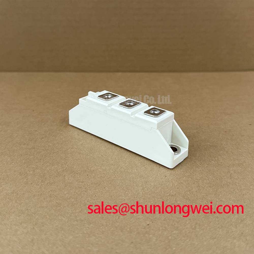
For a six-pulse or twelve-pulse electrolyzer supply, terminal connections should remain short, mechanically secure, and arranged to limit unequal current paths. The original mechanical drawing and installation instructions should determine fastener selection and tightening torque. Maintenance Note: Inspect heat-sink cleanliness, interface-material condition, terminal tightness, and contact temperature during scheduled service.
Field Diagnostics for Spark Gaps, MOVs, and RC Snubbers
Primary spark gaps, MOVs, and RC snubber networks are system-level protection components and are not specified as integrated functions of SKND105F12. For an AC input rectifier, the protection designer should assess the surge environment, transformer impedance, prospective fault current, wiring inductance, and the withstand capability of every series and parallel element. IEEE 61000-4-5 test objectives may be relevant to system testing, but the diode itself must not be described as independently EMC-certified.
During field diagnosis, compare the voltage across the diode with the original circuit waveform using suitable isolated measurement equipment. Check whether the MOV shows signs of thermal stress, whether the snubber resistor has changed value, and whether the capacitor retains its intended insulation and capacitance characteristics. Any abnormal reverse-voltage spike should be investigated against the 1200 V VRRM official rating and the complete transient protection design rather than assigned to one component without measurement.
The Semikron-Danfoss Power Electronics and Modules Official Hub provides manufacturer-level technology context. Engineers reviewing module integration methods may also consult Semikron-Danfoss SKiiP® Technology, while recognizing that SKND105F12 remains a power diode module product category.
DC Ripple Control in Six-Pulse and Twelve-Pulse Topologies
In a high-current green hydrogen electrolyzer DC power rectifier, six-pulse bridges can provide a straightforward conversion path, while twelve-pulse arrangements can reduce characteristic ripple when the transformer phase-shift and current-sharing network are correctly implemented. The choice is system-dependent and should be checked against output-current demand, transformer design, harmonic limits, cooling, and maintenance access.
Interphase transformers can support current sharing between bridge sections, but their magnetizing behavior, leakage impedance, saturation margin, and connection polarity require validation during commissioning. Measure DC output ripple, phase-leg current balance, diode case temperature, and reverse-voltage behavior under the intended operating profile. For a related Semikron reference in the same general power-semiconductor family, engineers may review SKT340/18E; this is a neutral technical comparison, not a substitute recommendation.
The 1.2 V maximum threshold voltage and 2.5 mΩ maximum slope resistance are official values specified at 130 °C. They can support conduction-loss assessment, but the completed bridge must still be tested with its real busbars, transformer, cooling system, and load. A possible upstream rectifier relationship can be evaluated alongside SKT240/18E. For broader field integration context, see Industrial Applications.
| Parameter | Official Datasheet Specification |
|---|---|
| Repetitive peak reverse voltage | 1200 V at Tvj = 25 °C |
| Continuous forward current | 105 A, sinusoidal 180°, Tc = 83 °C |
| Maximum RMS forward current | 200 A |
| Surge forward current | 2500 A for 10 ms at Tvj = 25 °C |
| I²t surge energy | 31,250 A²s |
| Peak forward voltage | 2.05 V at IF = 300 A, Tvj = 25 °C |
| Typical reverse-recovery time | 500 ns under specified test conditions |
| Thermal resistance | 0.24 K/W per diode; 0.12 K/W per module |



