


Content last revised on January 31, 2026
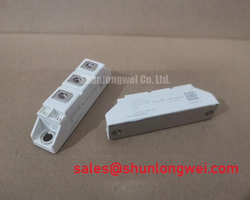
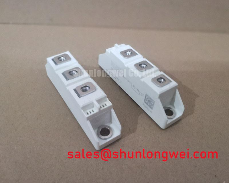
SKKD105F12: 1200V, 105A Diode Module for High-Reliability Rectifier Applications
Engineering Excellence for Demanding Power Systems
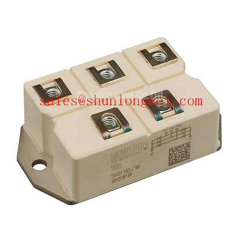
The Semikron SKKD105F12 is a half-bridge diode module engineered to deliver exceptional long-term reliability and simplified thermal management in high-current industrial rectifier applications. It integrates two rectifier diodes with key specifications of 1200V | 105A | IFSM 2500A. The module’s core advantages are its enhanced operational lifetime and robust thermal performance, stemming directly from its advanced construction. It directly addresses the engineering challenge of component failure in systems subject to frequent thermal cycling or mechanical vibration. For industrial rectifiers in thermally cycling environments, the SKKD105F12's pressure-contact design is the optimal choice for long-term reliability.
Application Scenarios & Value
Engineering System Longevity in Industrial Drives and Power Supplies
The SKKD105F12 is optimized for deployment in demanding power conversion systems where uptime and service life are critical operational parameters. Its robust design makes it a prime candidate for the input rectifier stages of Variable Frequency Drives (VFDs), DC motor drives, and high-power industrial battery chargers.
Consider the engineering challenge within a VFD controlling a conveyor belt system that frequently starts and stops. These cycles induce significant temperature swings within power components, leading to mechanical stress. In conventional soldered modules, this stress can cause solder layer fatigue and eventual bond wire lift-off, resulting in premature failure. The SKKD105F12 directly mitigates this failure mode through its pressure-contact design, ensuring a stable connection that is resilient to thermal cycling. What is the primary benefit of its pressure-contact design? Enhanced long-term reliability by eliminating solder fatigue. This makes it an ideal component for soft-starter circuits and industrial Uninterruptible Power Supply (UPS) systems, where reliability is paramount. For systems requiring higher current handling in a similar footprint, the related SKKD162/16 offers a 162A continuous current rating.
Key Parameter Overview
Datasheet Specifications for Robust Thermal and Electrical Design
The following parameters are critical for system design and integration. The values presented are based on the official manufacturer's datasheet, ensuring accuracy for engineering evaluations.
| Parameter | Symbol | Value | Unit | Conditions |
|---|---|---|---|---|
| Absolute Maximum Ratings | ||||
| Repetitive Peak Reverse Voltage | VRRM | 1200 | V | |
| Continuous Forward Current | IFAV | 105 | A | Tcase = 86 °C |
| Surge Forward Current | IFSM | 2500 | A | Tvj = 25 °C, 10 ms, sin. 50 Hz |
| I²t Value | I²t | 31250 | A²s | Tvj = 25 °C, 10 ms, sin. 50 Hz |
| Electrical Characteristics | ||||
| Forward Voltage | VF | 1.45 (max) | V | Tvj = 25 °C, IF = 400 A |
| Threshold Voltage | V(TO) | 0.85 (max) | V | Tvj = 150 °C |
| Slope Resistance | rT | 1.3 (max) | mΩ | Tvj = 150 °C |
| Reverse Current | IR | 5 (max) | mA | Tvj = 150 °C, VR = VRRM |
| Thermal and Mechanical Characteristics | ||||
| Thermal Resistance, Junction to Case | Rth(j-c) | 0.24 (max) | K/W | per diode, DC |
| Operating Junction Temperature | Tvj | -40 to +150 | °C | |
| Insulation Test Voltage | Visol | 3000 | V | a.c. 50 Hz; 1 s |
| Mounting Force | F | 6 ± 1 | kN | |
Download the SKKD105F12 datasheet for detailed specifications and performance curves.
Technical Deep Dive
A Closer Look at Pressure-Contact Technology for Eliminating Solder Fatigue
A key differentiator of the SKKD105F12 is its use of pressure-contact technology, a design philosophy central to high-reliability power modules. Unlike conventional modules that rely on soldered layers to connect the semiconductor die to the Direct Bonded Copper (DBC) substrate and the baseplate, this technology eliminates these critical solder interfaces. Instead, the semiconductor element is pressed between two molybdenum discs under high force, ensuring a robust and uniform electrical and thermal connection.
This can be compared to the difference between a glued joint and a high-force mechanical clamp. While the glued joint (solder) is effective initially, repeated expansion and contraction (thermal cycling) can cause it to fatigue, crack, and eventually fail. The mechanical clamp (pressure contact), however, maintains its integrity and consistent contact pressure despite these stresses. This design principle is fundamental to preventing the common wear-out failures seen in soldered modules, significantly extending the operational lifetime and reliability of the end system, a crucial factor in analyzing and preventing common causes of power module failure.
Frequently Asked Questions (FAQ)
Engineering Clarifications for Design and Implementation
What is the primary engineering benefit of the pressure-contact technology in the SKKD105F12?
The main benefit is a dramatic increase in power cycling capability and long-term reliability. By eliminating solder layers, which are a primary point of failure under thermal stress, the module is far more resistant to wear-out, making it ideal for applications with frequent on/off cycles or fluctuating loads.
How does the aluminium oxide ceramic baseplate simplify heatsink mounting and thermal design?
The aluminium oxide (Al₂O₃) ceramic baseplate provides excellent electrical insulation while facilitating efficient heat transfer. What is the isolation voltage of the SKKD105F12? It features 3000V electrical isolation. This allows the module to be mounted directly onto a grounded heatsink without needing an additional, thermally resistive insulation pad. This simplifies the mechanical assembly, reduces component count, and improves overall thermal performance by lowering the total thermal resistance (Rth) from the semiconductor junction to the ambient air.
Can the SKKD105F12 be used in parallel for higher current applications?
Yes, paralleling is possible, but it requires careful design considerations. According to the manufacturer's documentation, only modules from the same forward voltage drop class should be connected in parallel to ensure proper current sharing. It is critical to consult the datasheet for detailed application notes on paralleling to ensure a balanced and reliable system design.
To discuss the suitability of this module for your specific application or to request more information, please contact our technical team with your project details.