Content last revised on September 16, 2026
SKKD162/20H4 Specifications and Initial Inspection
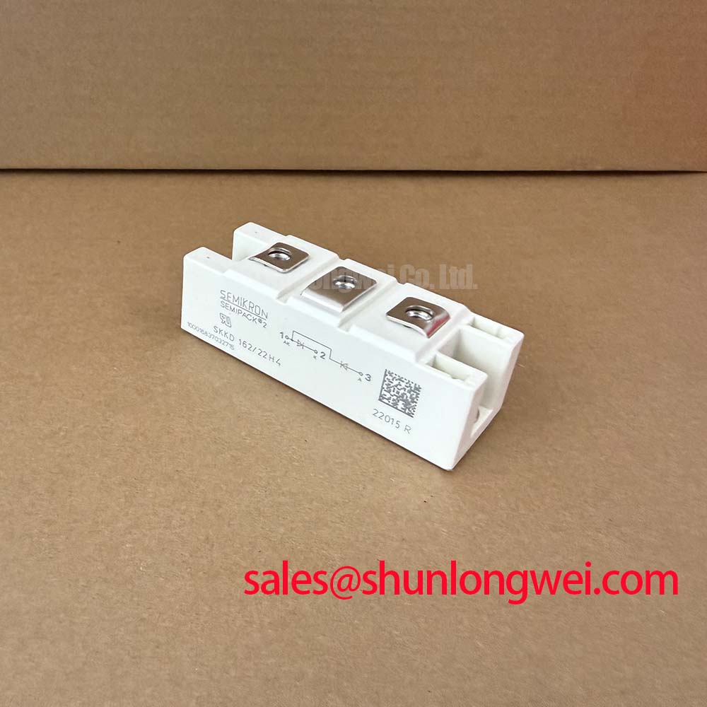
With the power circuit isolated, first verify the module marking and check each accessible power path with a suitable diode test method before reconnecting the DC bus. SKKD162/20H4 is a Semikron SEMIPACK 2 diode module with an isolated metal baseplate. Its official ratings are 2000V VRRM, 160A IFAV at TC = 85°C, 4700A IFSM at 10ms and 25°C, 0.18 K/W Rth(j c), and 3600V AC isolation for one minute at 50Hz.
| Technical specification | Official value or rating |
|---|---|
| Repetitive peak reverse voltage, VRRM | 2000V |
| Mean forward current, IFAV, at case temperature 85°C | 160A |
| Surge forward current, IFSM, 10ms at 25°C | 4700A |
| Thermal resistance, junction to case, Rth(j c) | 0.18 K/W |
| Isolation voltage, AC 50Hz for one minute | 3600V |
| Package and baseplate | SEMIPACK 2 with isolated metal baseplate |
These are Official Datasheet Specifications. They establish the electrical and thermal identity of the module, but they do not replace verification of the equipment circuit diagram, conductor arrangement, heatsink condition, fuse documentation, or the original controller logic.
Benchtop Waveform Tuning: Mitigating Stress via Phase-Controlled Rectification on SKKD162/20H4
Start waveform work by separating the diode module from any controlled semiconductor stage in the surrounding cabinet. The SKKD162/20H4 has no gate terminal and does not set a firing angle. A diode rectifier conducts according to the instantaneous polarity imposed by the AC source and connected circuit. Therefore, an alpha range from zero to 150 degrees cannot be assigned to this module as an Official Datasheet Specification or used to derive its own phase control characteristic.
In a high voltage three phase motor solid state soft starter, a phase controlled thyristor assembly can change conduction timing and influence supply current waveform, displacement factor, reactive demand, and harmonic content. The diode section may instead be evaluated as part of the supporting rectification, freewheel, bypass, or polarity management arrangement defined by the equipment schematic. Engineers should capture phase voltage, phase current, and DC link behavior with reference to the known control sequence, then determine whether observed stress originates in the controlled stage, commutation path, supply imbalance, or load condition.
The 2000V VRRM rating is the official repetitive reverse voltage boundary for this module. Design Consideration: inspect transient behavior at the installed electrical location, because cable inductance, commutation conditions, transformer leakage, and protection layout determine actual voltage excursions. The measured peak must be assessed against the system voltage boundary rather than assumed from nominal line voltage alone.
For equipment using separate controlled power modules, a device such as SKKT 250/14E can be reviewed as a neutral system topology reference where the original circuit documentation identifies that device family. It is not a declared substitute for SKKD162/20H4. The circuit symbol, terminal designations, current direction, and thermal interface must remain consistent with the original repair design.
Semikron’s SEMIPACK thyristor and diode module information provides useful product family context when confirming the role of packaged power semiconductors. Before energizing a repaired assembly, compare the installed module’s terminal use with the machine drawing instead of inferring topology from package format.
SKKD162/20H4 Circuit Protection & Reliability: Sub-Cycle Dead-Short Coordination
A sub cycle dead short evaluation begins with the semiconductor fuse data sheet and the original protection coordination drawing. The official 4700A IFSM rating describes a specified nonrepetitive forward surge condition of 10ms at 25°C. It is not a published fuse clearing I²t value, not a guaranteed fault clearing capability, and not enough information to calculate Type 2 coordination for a particular starter panel.
Engineering Recommendation: obtain the fuse pre arcing I²t, total clearing I²t, prospective fault current, source impedance, conductor contribution, and the relevant protective coordination requirements before approving a replacement module for a dead short duty. The protection path must be assessed as a system. Fuse operation, contactor behavior, busbar geometry, upstream transformer capacity, and the fault location all influence the energy reaching the diode junctions.
Where the original cabinet uses semiconductor fuses, inspect fuse holders, contact pressure, conductor discoloration, and the continuity of the intended current path while isolated. A mechanically sound fuse can still be unsuitable if its documented clearing characteristics differ from those specified for the equipment. Do not use the module’s 160A mean forward current rating at 85°C case temperature as a fuse selection number. That current rating depends on the stated thermal condition and does not describe fault interruption performance.
The isolated metal baseplate has an Official Datasheet isolation rating of 3600V AC at 50Hz for one minute. This rating must not be presented as a whole equipment safety certification. Design Consideration: insulation verification should follow the equipment manufacturer’s test procedure, with the module removed from any test arrangement that could expose connected control electronics or measurement circuits to an unintended test potential.
For comparison during system documentation review, SKKT500/14E can be considered as a separate power module reference with its own ratings and circuit configuration. Any mechanical or electrical interchange decision requires the original schematic, mounting pattern, thermal requirements, and protection coordination evidence.
Transient Dynamics & Electrical Design: Preventing Localized Hotspot Burnout on SKKD162/20H4
There is no gate firing pulse, gate current rise time, holding current, Miller plateau, desaturation threshold, or active clamp function inside the SKKD162/20H4 diode module. Those terms apply to controlled devices such as thyristors, IGBTs, or MOSFETs and must be evaluated at the actual device performing the switching function. Applying gate drive settings intended for another semiconductor to this diode module would be technically invalid.
That distinction matters during fault investigation. A distorted current waveform, irregular soft start ramp, or excess heating in the diode path may coexist with an issue in the thyristor firing board, synchronisation circuit, snubber network, sensor feedback, or line supply. It does not establish a single cause. Verify control pulses at the controlled devices with a properly referenced measurement method, then compare the power current waveform against the machine’s expected operating state.
Design Consideration: keep the high current commutation path compact and mechanically secure to reduce parasitic inductance that can add voltage overshoot during current transition. The required layout, snubber arrangement, and verification limits are system determined. Engineers should validate peak voltage and current behavior under representative switching and fault test conditions while remaining within the installed equipment’s approved test process.
⚠️ Field Alert: Do not apply a presumed gate drive setting or gate test signal to SKKD162/20H4 because this diode module has no gate connection.
For engineers comparing switching device behavior elsewhere in an industrial drive or controlled power cabinet, Unlocking Efficiency in Industrial Drives offers supporting technical context; its IGBT focused discussion must not be used to reinterpret the diode module’s official ratings.
Field Diagnostics & Commissioning: Mechanical Mounting, Thermal Management, and Commissioning for SKKD162/20H4
Inspect the heatsink face before mounting the module. Remove residue that prevents flat contact, check for local damage around mounting areas, and confirm that the baseplate sits evenly before hardware is tightened. The official junction to case thermal resistance is 0.18 K/W. This value describes the thermal path from semiconductor junction to case under the manufacturer’s specified conditions; it does not include thermal interface material, heatsink resistance, airflow, enclosure temperature, or load waveform.
A transient thermal impedance curve cannot be derived from the published steady state 0.18 K/W Rth(j c) value alone. When pulsed junction temperature margin is required, the system integrator should obtain the relevant manufacturer thermal transient data or validate the assembled system with an approved thermal measurement method. Avoid estimating junction temperature from case temperature alone when current is cyclic or when the load profile contains repeated surges.
Apply thermal interface material as a continuous, controlled layer suitable for the heatsink finish and the equipment procedure. The supplied official parameters do not state a mounting torque or tightening sequence for this exact module. Engineering Recommendation: use the torque and hardware sequence in the applicable Semikron mechanical documentation or original equipment service instructions, tighten progressively to maintain even contact pressure, and avoid baseplate distortion.
During commissioning, record case temperature, line current, current balance between phases where applicable, and the voltage waveform across the installed power section. A rising temperature trend may indicate restricted cooling, degraded interface contact, abnormal current sharing, or a changed operating duty. Correlating these measurements with the original control state gives a more reliable repair decision than treating any single temperature or resistance reading as conclusive.