Content last revised on October 7, 2026
Gate Trigger Current (I_GT) Temperature Dependency and Back-Porch Holding Requirements
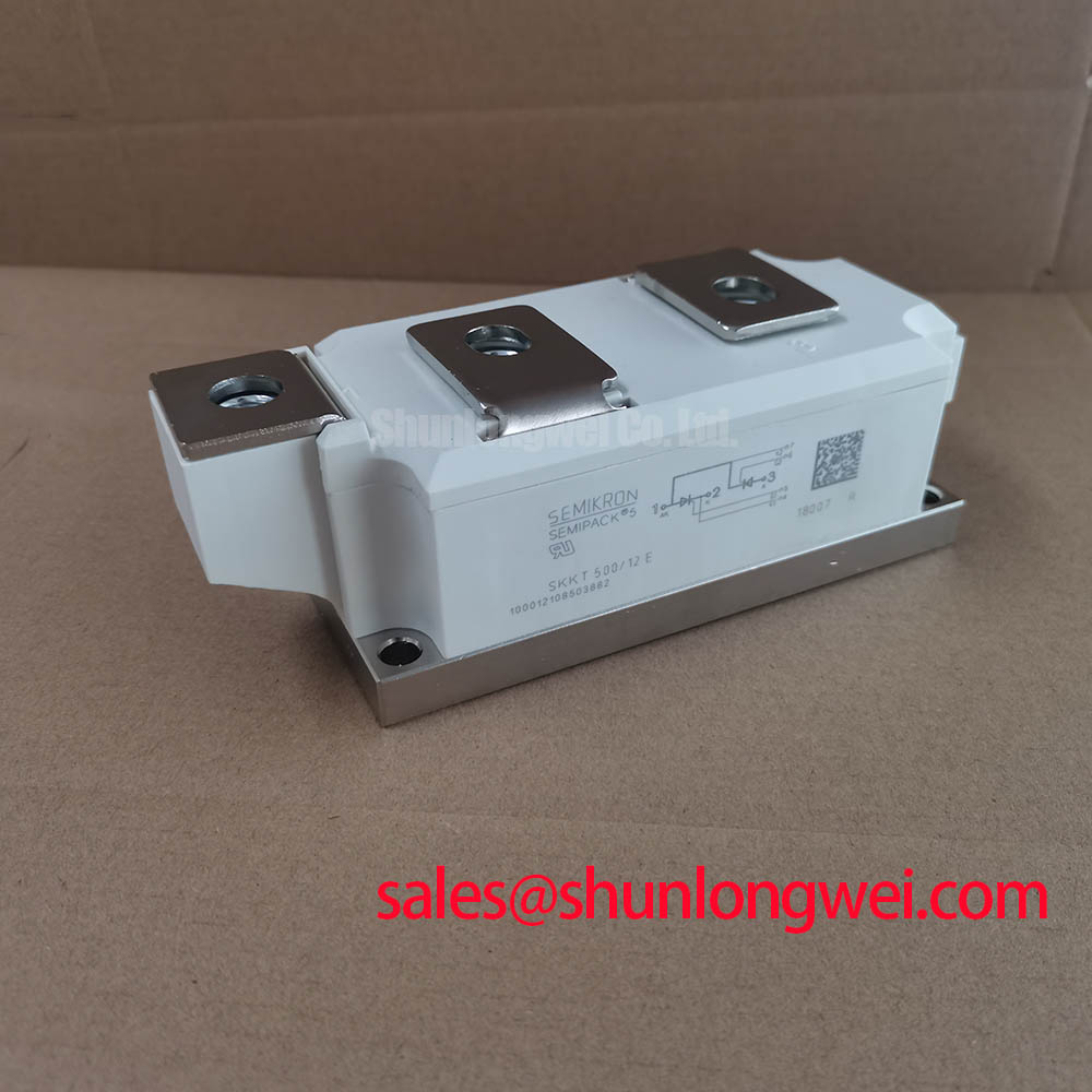
With the soft starter isolated and discharged, check the gate-to-cathode path and the power-terminal connections of the SKKT106-12E-2 against the original wiring diagram before reconnecting its firing board. A healthy cold resistance reading alone does not establish that a thyristor will fire reliably: gate trigger current changes with junction temperature, and the driver must still deliver an effective pulse under the least favorable operating conditions specified for the exact device variant.
In a three-phase motor soft starter, each firing command must coincide with the intended phase voltage and current direction. Review the gate pulse at the module terminals rather than only at the controller output. Cable resistance, connector condition and shared return paths can change the pulse delivered to the device. The initial pulse must establish conduction across the thyristor before the gate drive falls away; a back-porch or repeated-pulse strategy may help maintain triggering while motor current is still building. Pulse shape, amplitude and duration should be checked against the applicable Semikron datasheet and the installed driver design, not assigned generic values.
During a repair, compare the firing waveform and phase-current trace with those of the other functioning phases at comparable operating conditions. A missing current segment may involve the gate circuit, the power connection or the controller’s firing timing. The Semikron Danfoss SEMIPACK thyristor and diode module information identifies the product family; the exact variant documentation remains the reference for terminal assignments and electrical limits.
Junction-to-Case Thermal Resistance (R_th(j-c)) & Mounting Clamping Torque Calibration
Remove old thermal-interface material, inspect the heatsink for raised edges or debris, and seat the SEMIPACK housing without forcing its terminals into alignment. Even contact matters because junction-to-case thermal resistance is only one part of the heat path. The installed thermal performance also depends on the interface material, heatsink condition, airflow and current waveform.
Apply thermal-interface material according to the module and heatsink instructions, then tighten the mounting hardware in the specified sequence with a calibrated tool. Obtain the mounting torque from the documentation for the exact module and hardware combination; a generic fastener torque is not a substitute. Check that busbar connections do not pull on the housing after the mounting screws are tightened. Terminal connection torque must likewise come from the applicable assembly instructions.
⚠️ Field Alert: Do not use a busbar bolt to pull a misaligned terminal into place, because that can impose mechanical stress on the mounted module.
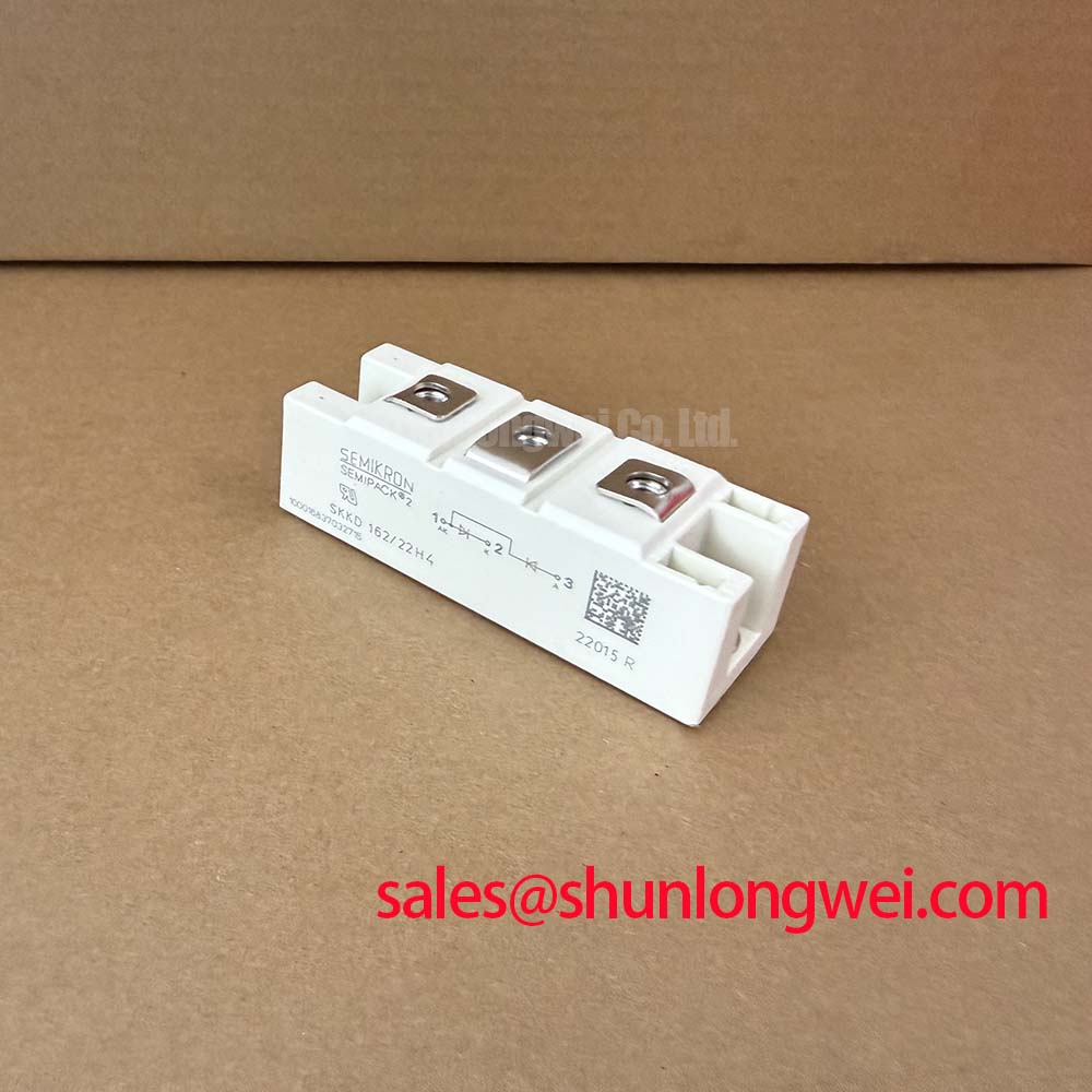
For an operating unit, compare heatsink and terminal temperatures across phases under a repeatable load. A temperature difference is a reason to inspect contact pressure, electrical connections and phase-current balance; it does not by itself identify a failed module. If a replacement candidate is being assessed, compare its terminal layout, mounting footprint and documented thermal limits as well as its electrical ratings. The SKKD162/12 can be included in that comparison, but its diode-module function must not be treated as interchangeable with thyristor phase control.
Evaluating Post-Surge Reverse Voltage Blocking Recovery at Elevated Junction Temperatures
After an overload or upstream fault, isolate the starter and examine its recorded phase currents, protection operation and cooling status before testing the SKKT106-12E-2. A surge-current rating applies under its stated waveform and initial-temperature conditions. It does not establish that a device exposed to an unknown fault can immediately resume blocking reverse voltage at the previous operating temperature.
Review the exact datasheet’s surge-current conditions and fuse-coordination information alongside the installed fuse’s clearing characteristics. A fuse with an appropriate continuous-current rating still needs its clearing energy evaluated against the semiconductor limits for the relevant fault conditions. Where the documentation or event record is incomplete, do not infer a remaining thermal margin from the fact that the fuse opened.
With power removed, compare blocking behavior and leakage indications using an approved test method and the manufacturer’s specified limits. A low-voltage handheld check may reveal a gross short but cannot verify the full blocking rating. Before return to service, confirm that the starter’s line transients, firing sequence and cooling arrangement remain within documented device and system limits. The Field Engineer’s Handbook provides a practical reference for structuring isolation and comparison checks; the module datasheet governs acceptance limits.
Mechanical Torque Shock Elimination in Heavy Pumps and Compressors via Soft Ramping
For a pump or compressor starter, inspect the motor nameplate, load characteristics and current feedback before changing the phase-angle ramp. The module’s job is to switch the controlled AC path when commanded; the starter controls how conduction develops over successive half-cycles. A smoother current rise can reduce abrupt shaft loading, but no module rating alone guarantees a particular inrush-current reduction or eliminates mechanical shock.
Trend phase currents and the available speed or process feedback during a supervised start. If one phase conducts late or intermittently, investigate its firing signal and power connections before lengthening the ramp: a control change can conceal a phase-specific fault. Set the ramp and protection thresholds from the motor, load and starter documentation, then verify them during commissioning under representative operating conditions.
When reviewing the wider power circuit, distinguish controlled thyristor positions from rectifier positions on the schematic. The SKKT273/12E is another thyristor module that can be evaluated where its documented topology, ratings and mechanical arrangement suit a separate circuit position; it is not an automatic substitution for the SKKT106-12E-2. Before releasing the starter, confirm the exact module variant’s voltage, current, surge, thermal and mounting specifications against its manufacturer datasheet and the equipment’s original bill of materials.