

Content last revised on September 18, 2026
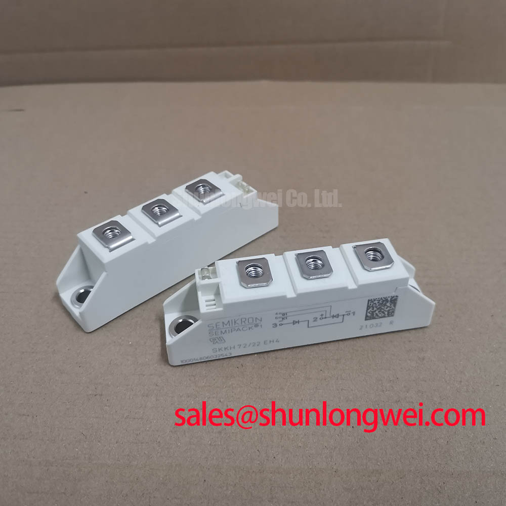
Field Diagnostics & Commissioning: Dynamic Voltage Sharing and RC Damping in SKKH72/22EH4 Topologies
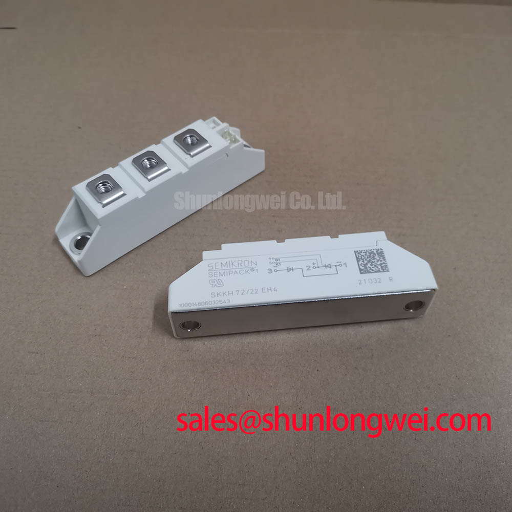
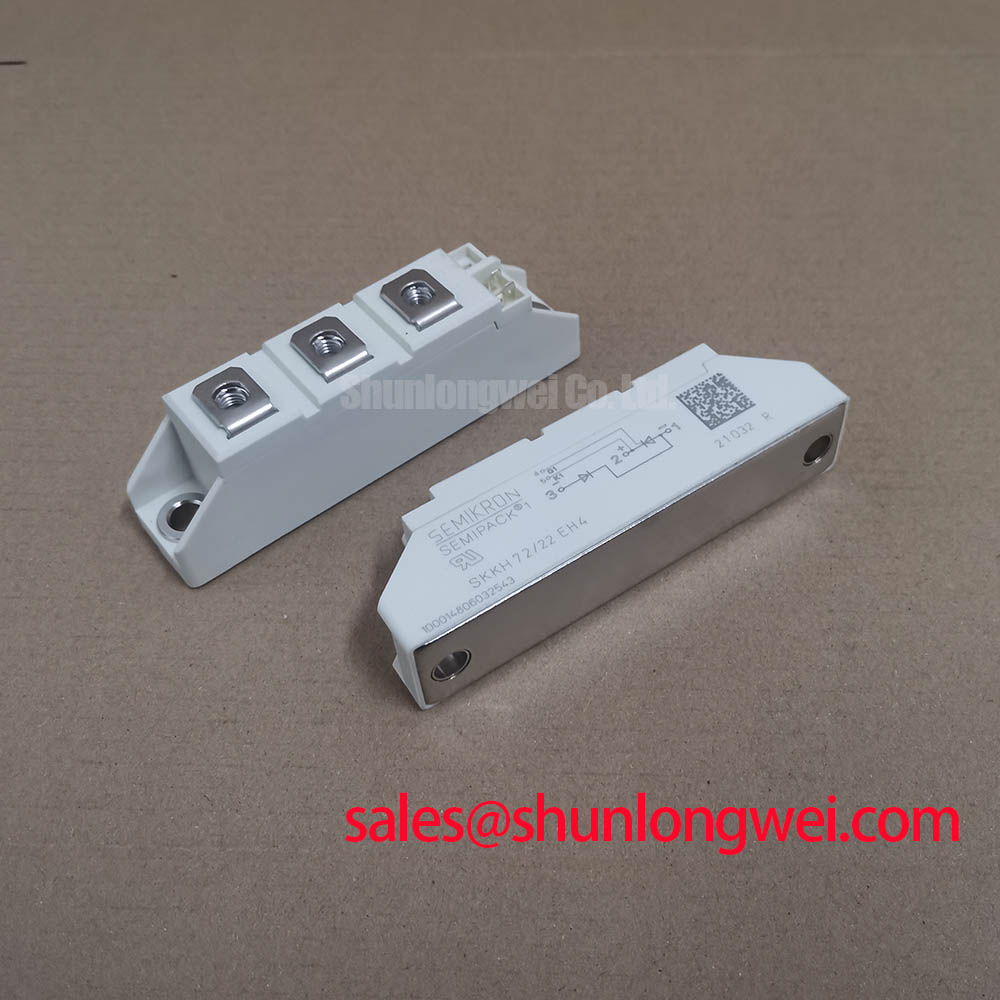
Start commissioning with a de-energized continuity and insulation-path inspection of the complete controlled-rectifier branch, rather than evaluating the module in isolation. Confirm that busbars, fuse links, RC damping parts, gate leads, and measurement references correspond to the schematic revision fitted to the equipment. A high-current electrolyzer DC rectifier can contain several parallel or series-connected power paths, so voltage sharing depends on the surrounding network as well as the condition of the SKKH72/22EH4 module.
RC damping networks and series saturable reactors are Design Considerations, not declared factory features of this module. Their purpose in a controlled topology is to limit transient stress caused by commutation-loop inductance and to reduce conditions that could lead to unintended thyristor triggering. Engineers should inspect capacitor condition, resistor connections, and reactor placement, then capture anode-to-cathode voltage and branch current during controlled test pulses. The acceptance criteria must be established by the rectifier designer, using the actual DC-link condition and the documented device limits.
Fuse selection also requires the original coordination information. Do not infer a fuse I²t relationship from the stated 2200 V and 72 A ratings alone. Review the installed fuse documentation, its clearing behavior, the expected fault path, and the module documentation as a combined protection set. A replacement review may include the linked SKKD81/14 as a reference point for catalog comparison, but its circuit function, ratings, connection format, and thermal interface must be evaluated independently.
💡 Pro Tip: Keep commutation busbars physically paired and symmetrical where practical, then verify transient voltage at the installed terminals during controlled switching tests.
Assembly Integrity & Layout Architecture: Implementing Non-Repetitive Surge On-State Current for SKKH72/22EH4
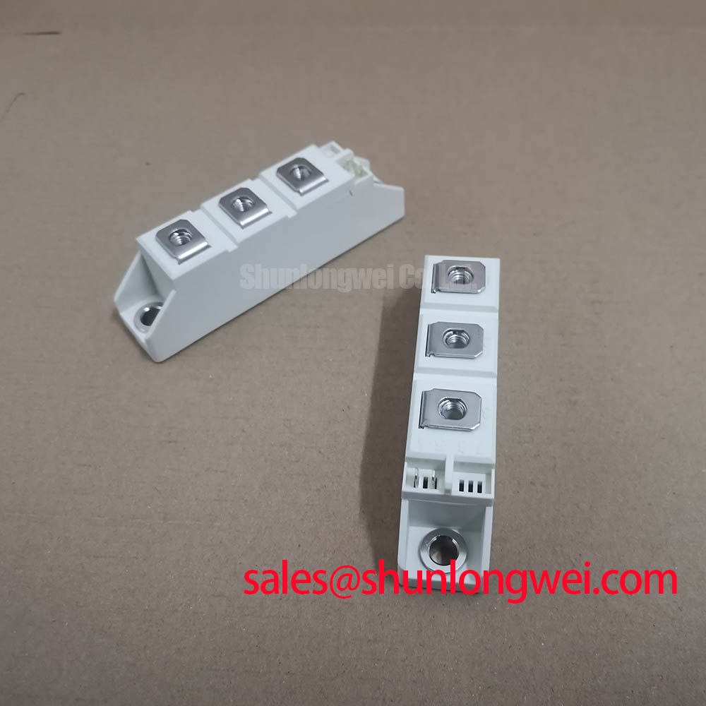
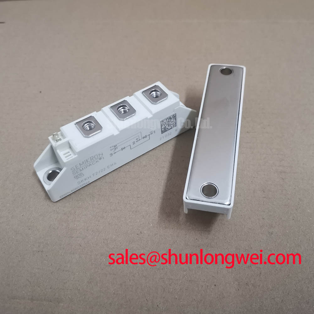
Inspect the Semipack housing, terminal hardware, busbar contact faces, and heatsink interface before applying a non-repetitive surge test. Loose joints, oxidized contact surfaces, unequal busbar pressure, and a distorted mounting surface can alter current distribution and create local heating that is not visible in a static resistance check. The stated 72 A figure is an Official Specification current rating in the supplied product record; it is not a substitute for an authorized sinusoidal half-cycle surge-current limit.
The requested 10 ms half-cycle surge analysis must therefore remain tied to the applicable manufacturer surge table. Before reverse voltage is reapplied after a fault event, technicians should verify the thermal recovery condition of the full branch, inspect the fuse path, and compare waveform captures with a known serviceable channel where available. A surge event can affect clamping components, connectors, and laminated bus structures as well as the semiconductor module.
Mounting torque is likewise not available in the supplied official data. Use only the torque value specified for the particular Semipack case and the installed screw, washer, and heatsink arrangement. This is an Engineering Recommendation: tighten terminals and baseplate hardware in the equipment maker’s specified sequence and verify even mechanical contact rather than applying a generic torque value. The Semikron SEMIPACK® thyristor and diode module information provides useful product-family context, while the exact device documentation remains the authority for installation limits.
SKKH72/22EH4 Operational Boundaries: Evaluating Pulse-Transformer Isolated Firing Circuit Limits
For a controlled thyristor circuit, evaluate the pulse-transformer firing path from the control-board output through the isolation barrier to the module gate connection. Confirm the polarity, connector assignment, lead routing, and firing sequence against the original rectifier schematic before applying power. The supplied product data does not declare gate trigger current, gate pulse rise-time limits, holding-current behavior, or permissible gate dissipation for SKKH72/22EH4. Those values must not be estimated from a similar Semipack device.
Pulse rise behavior, back-porch support, and multi-pulse firing are Design Considerations determined by the thyristor gate specification, transformer transfer behavior, cable inductance, and the rectifier’s commutation conditions. A slow or poorly referenced firing pulse may contribute to inconsistent triggering, while excessive gate energy can create avoidable stress. Use isolated voltage and current measurements to compare the firing waveform at the driver output and at the module-side connection, with test limits defined by the original design documentation.
Keep gate and control return paths separate from high-current power-loop conductors to reduce common-mode disturbance into the firing circuit. If the rectifier uses optical or digital isolation upstream of the pulse transformer, assess its transient immunity within the whole installed circuit rather than assigning an EMC or isolation certification claim to the module. For related system-level principles covering gate-drive coordination, thermal interfaces, and power-loop layout, consult IGBT Design & Integration as an engineering reference.
Field Diagnostics & Commissioning: Harmonic Current Injection and Line Filter in SKKH72/22EH4 Topologies
During commissioning of a high-current green hydrogen electrolyzer DC power rectifier, record incoming line voltage, phase current, DC output current, firing reference, and DC ripple while firing angle is varied within the permitted controller range. Controlled rectifiers alter real-power transfer and reactive-power demand as firing angle changes. The resulting harmonic profile depends on transformer impedance, line inductance, filter configuration, DC load behavior, commutation overlap, and the number of rectifier pulses. It cannot be determined from the module’s declared 2200 V and 72 A ratings.
Line filters, AC reactors, MOV networks, and snubber assemblies should be inspected as connected system elements. A rising harmonic reading or unexpected DC ripple may indicate several possible conditions, including changed firing synchronization, imbalance between branches, degraded filtering, altered source impedance, or an issue in the measurement chain. Validate the observation with calibrated instruments and compare it against the equipment manufacturer’s baseline waveform or a healthy parallel channel.
Where a related controlled device is present in the same supply architecture, the SKKT 250/14E can be reviewed as a separate catalog item for system documentation purposes. It should not be treated as an automatic replacement for SKKH72/22EH4. Any compatibility decision requires verification of circuit topology, terminal layout, firing requirements, voltage blocking conditions, thermal path, protection coordination, and the equipment maker’s approved service procedure. Semikron’s CAL diode technology information may also assist broader semiconductor technology research, but it does not establish operating limits for this specific module.