


Content last revised on February 3, 2026
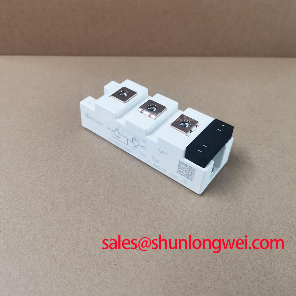
FF100R12RT4: 1200V 100A Dual IGBT Module Engineered for High-Frequency Switching Stability
Executive Summary: Key Engineering Features
A Datasheet-Driven Overview for Power System Designers
The FF100R12RT4 is a 1200V, 100A dual IGBT module featuring Infineon TRENCHSTOP™ IGBT4 and Emitter Controlled 4 diode technology, optimized for high-frequency power conversion systems. With core specifications of 1200V | 100A | VCE(sat) (typ.) 1.75V, this module delivers robust thermal performance and minimized switching losses. It is engineered for low stray inductance and features an extended maximum operating temperature of 150°C. How does the positive temperature coefficient of VCE(sat) benefit system design? It inherently aids in balancing current when paralleling modules, simplifying the design of higher-power inverter stages. For industrial motor drives requiring robust performance under 50kW, the FF100R12RT4's combination of low switching losses and thermal stability makes it a strategically sound choice.
Application Scenarios & Value
Achieving System-Level Benefits in Demanding Power Conversion Environments
The FF100R12RT4 is engineered for deployment in high-frequency applications where efficiency and thermal stability are critical design drivers. Its characteristics make it particularly suitable for industrial Variable Frequency Drive (VFD) systems, high-power converters, and uninterruptible power supplies (UPS). A primary engineering challenge in these applications is managing switching losses, which escalate with frequency and directly impact system efficiency and cooling requirements. The TRENCHSTOP™ IGBT4 technology within the FF100R12RT4 directly addresses this by optimizing the turn-on (Eon) and turn-off (Eoff) energy. This results in lower overall power dissipation, enabling designers to either increase the operating frequency for smaller magnetic components or reduce the heatsink size, thereby improving power density and lowering bill-of-materials (BOM) costs. While the FF100R12RT4 is a strong fit for a wide range of applications, for systems that demand higher current handling, the FF150R12RT4 offers a 150A capability within a similar technological framework.
Key Parameter Overview
Decoding the Specs for Enhanced Switching Performance
The technical specifications of the FF100R12RT4 are tailored for robust performance in high-frequency switching circuits. The table below highlights key parameters derived directly from the official datasheet, with an emphasis on metrics critical for evaluating efficiency and thermal behavior.
| Parameter | Conditions | Value | Engineering Significance |
|---|---|---|---|
| Collector-Emitter Voltage (VCES) | Tvj = 25°C | 1200 V | Provides the necessary voltage margin for standard industrial bus voltages, ensuring reliability against transient overvoltages. |
| Nominal Collector Current (IC nom) | TC = 100°C, Tvj max = 175°C | 100 A | Defines the module's continuous current handling capability at a high case temperature, crucial for thermal design. |
| Collector-Emitter Saturation Voltage (VCE(sat)) | IC = 100 A, VGE = 15 V, Tvj = 25°C | Typ. 1.75 V | Max. 2.05 V | A low VCE(sat) directly translates to lower conduction losses, which is a major factor in the module's overall efficiency. This is akin to having lower resistance in a simple circuit, minimizing heat generation. |
| Total Switching Energy (Ets) | IC = 100 A, VCE = 600V, VGE = ±15V, RGon = 4.7 Ω, RGoff = 4.7 Ω, Tvj = 125°C | Typ. 12.00 mJ | This parameter is the sum of turn-on and turn-off energy and is the primary determinant of switching losses. Its low value is essential for efficient operation at higher frequencies. |
| Virtual Junction Temperature (Tvj op) | Operating | -40 to 150 °C | A wide operating temperature range, with a high maximum of 150°C, provides a significant thermal margin for demanding industrial environments. |
Download the FF100R12RT4 datasheet for detailed specifications and performance curves.
Technical Deep Dive
Analyzing the TRENCHSTOP™ IGBT4 and Emitter Controlled 4 Diode Combination
The core of the FF100R12RT4's performance lies in the synergy between its TRENCHSTOP™ IGBT4 and the Emitter Controlled 4 freewheeling diode. The IGBT4 technology represents a significant optimization point between conduction and switching losses. Unlike earlier generations that might excel at one metric at the expense of the other, IGBT4 provides a more balanced profile. This balance is critical for applications like motor drives that experience a wide range of operating conditions. The positive temperature coefficient of the VCE(sat) is a key reliability feature; as a chip heats up, its on-state resistance effectively increases, which naturally discourages any single chip in a paralleled array from "hogging" current and entering thermal runaway. This self-balancing behavior simplifies the paralleling of modules for higher power output. The accompanying Emitter Controlled 4 diode is engineered for soft recovery characteristics. This "softness" reduces voltage overshoots and oscillations during diode turn-off, which in turn minimizes electromagnetic interference (EMI). For a system designer, this means less filtering is required to meet EMC standards like IEC 61800-3, saving board space and component cost.
Frequently Asked Questions (FAQ)
Engineering-Focused Inquiries for the FF100R12RT4
What is the primary benefit of the low typical switching energy (12.00 mJ)?
The low total switching energy directly reduces power loss during the turn-on and turn-off transitions. This is especially critical in higher-frequency applications (e.g., >8 kHz), as it lowers the thermal load on the module and the heatsink, enabling more compact and efficient system designs.
How does the VCE(sat) positive temperature coefficient affect paralleling?
The positive temperature coefficient means that as the IGBT heats up, its on-state voltage drop increases. When modules are connected in parallel, if one module starts to carry more current and heat up, its rising VCE(sat) will naturally cause current to redistribute to the cooler modules. This inherent self-balancing mechanism improves the reliability and simplifies the design of high-current power stages without requiring complex external sharing components.
What does the 150°C maximum operating junction temperature imply for system design?
A higher maximum Tvj op provides a greater thermal design margin. It allows the module to operate safely under more demanding load cycles or in higher ambient temperatures. This robustness can translate to a smaller required heatsink or a higher power output for a given cooling solution, enhancing the overall power density of the end application.
Strategic Implications
Integrating the FF100R12RT4 allows designers to develop power conversion systems that are not only efficient but also compact and reliable. The module's balanced performance, stemming from the TRENCHSTOP™ IGBT4 technology, provides a solid foundation for next-generation industrial drives and power supplies that must meet stringent efficiency standards and operate reliably in harsh environments. This module represents a strategic choice for engineers looking to optimize system cost and performance without compromising on long-term dependability.