

Content last revised on September 20, 2026
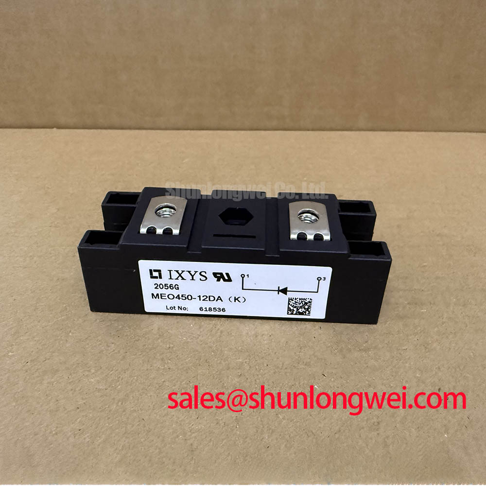
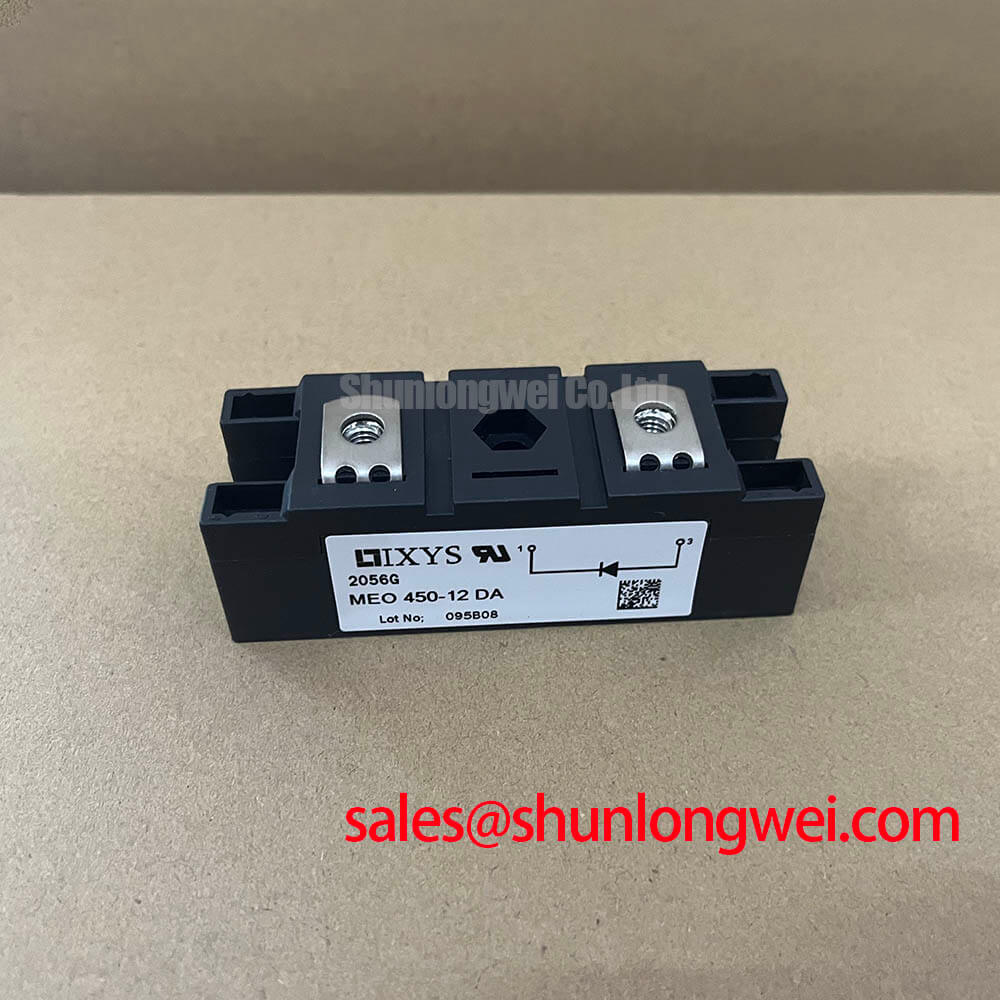
MEO450-12DA Specifications and Inspection
Verify the nameplate marking, inspect the power terminals and insulating surfaces, and confirm the rectifier assembly is deenergized before measuring any terminal-to-terminal resistance. The IXYS MEO450-12DA is a dual diode module intended for high-current rectification, with a repetitive peak reverse voltage of 1200 V and an average forward current rating of 486 A under the stated case-temperature and conduction conditions.
| Parameter | Symbol | Official Datasheet Specification |
|---|---|---|
| Repetitive peak reverse voltage | VRRM | 1200 V, TVJ from −40 °C to 150 °C |
| Average forward current | IFAV | 486 A at TC = 85 °C, 180° rectified |
| RMS forward current | IFRMS | 760 A |
| Surge forward current | ITSM | 15000 A, TVJ = 150 °C, 10 ms, 50 Hz sine wave |
| Fusing I²t value | I²t | 1125 × 10³ A²s at TVJ = 150 °C and 10 ms |
| Threshold voltage | VT0 | 0.85 V, for power loss calculation only |
| Forward slope resistance | rT | 0.45 mΩ, for power loss calculation only |
| Junction-to-case thermal resistance | RthJC | 0.08 K/W per diode |
| Operating junction temperature | TVJ | −40 °C to 150 °C |
| Isolation test voltage | VISOL | 3000 V RMS at 50/60 Hz for 1 minute |
Transient Dynamics & Electrical Design: Type 2 Coordination for Subcycle Short Circuit Protection
For a high-current green hydrogen electrolyzer DC power rectifier, the first protection review should compare the prospective fault current, the semiconductor fusing requirement, and the diode module’s published surge capability. The MEO450-12DA carries an official ITSM rating of 15000 A for the specified 10 ms half-cycle condition. This is a withstand rating for the stated test condition, not a permission to operate continuously at that current.
Fuse coordination should be verified using the selected semiconductor fuse manufacturer’s let-through I²t data. The module’s published 1125 × 10³ A²s fusing value provides a comparison point, but it does not by itself select a fuse or prove Type 2 coordination. The engineer should check the fuse clearing time, prospective short-circuit current, peak let-through current, installation impedance, and the thermal state of the diode at the time of the fault. A coordination table specific to the fuse family and rectifier topology is required before production approval.
Terminal connections deserve the same attention as the fuse calculation. Keep the high-current paths short and symmetrical where the bridge layout permits, and verify that busbar contact surfaces are clean, flat, and properly supported. The supplied specifications do not state a mounting torque value, so the system integrator should use the original IXYS mechanical documentation or the approved assembly drawing rather than applying an assumed torque. After assembly, inspect for uneven contact pressure and measure the phase-to-phase resistance against a known-good assembly using an appropriate low-resistance method.
The module’s RthJC of 0.08 K/W per diode is an official thermal parameter, not the complete heatsink design value. Case temperature, interface material, clamping arrangement, airflow or coolant conditions, and current sharing between parallel paths must be evaluated together. The junction operating boundary remains −40 °C to 150 °C; the thermal design should be validated with measured case temperatures and the actual rectifier duty cycle.
MEO450-12DA Operational Boundaries: Evaluating Off State Voltage Rate of Rise
The MEO450-12DA is a diode module, so gate-trigger parameters such as IGT and VGT do not apply to this product. In a controlled rectifier cabinet, however, it may operate beside thyristors, snubber networks, and commutation components. The relevant design task is to control voltage transients across the diode and confirm that the actual peak reverse voltage remains within the official 1200 V VRRM boundary under the worst switching and line conditions.
An RC snubber or series saturable reactor may be considered when measured voltage overshoot or commutation behavior indicates excessive electrical stress. The component values must be determined from the system’s source impedance, transformer leakage, busbar geometry, operating frequency, load profile, and measured waveform. This is a Design Consideration, not an IXYS factory specification. Designers should verify the result with a properly rated differential probe and compare the waveform at the module terminals, rather than relying only on a remote DC-link measurement.
Parasitic inductance in the commutation loop can increase local voltage overshoot and current concentration. Reduce unnecessary loop area, maintain balanced conductor geometry, and keep snubber connections physically close to the power terminals. The external ROHM SOA application guidance can support general semiconductor stress analysis, but it does not establish the MEO450-12DA’s own ratings or certify a particular rectifier design.
🔧 Bench Diagnostic: Isolate the DC bus and allow the specified discharge process to complete before disconnecting power terminals or attaching oscilloscope probes.
For assemblies using phase-controlled devices upstream or downstream, pulse timing and commutation overlap should be reviewed separately from the diode’s static voltage rating. The module should not be assigned a thyristor gate-control function unless the complete circuit documentation identifies a separate controlled semiconductor stage.
Field Diagnostics & Commissioning: Reverse Recovery in Rectifier Topologies
Reverse recovery behavior influences commutation loss, voltage ringing, and electromagnetic emissions, but the supplied factory data for this product does not specify reverse-recovery charge, reverse-recovery time, or peak reverse-recovery current. Those values must not be inferred from the forward-current rating. During commissioning, record the current and voltage waveforms at the module terminals under the intended transformer, busbar, load, and switching conditions.
A useful diagnostic sequence begins with a visual inspection of the power connections and isolation barriers, followed by a cold electrical comparison with a known-good module removed from the circuit. If the waveform shows unusual current overlap, ringing, or unequal phase loading, investigate commutation inductance, transformer leakage, snubber condition, fuse connection quality, and measurement-loop placement before attributing the behavior to the diode itself.
The official forward-loss parameters provide a practical starting point for thermal estimation. The published threshold voltage is 0.85 V and the forward slope resistance is 0.45 mΩ, both identified for power-loss calculation only. Actual loss evaluation should use the measured current waveform and the manufacturer’s applicable forward-characteristic curves where available. The result should then be checked against the module case temperature and the cooling assembly.
Control and monitoring networks can affect the timing of a rectifier cabinet without proving semiconductor compliance. For example, Ethernet Powerlink is a deterministic industrial network standard, but the MEO450-12DA should not be described as certified to that network standard. Any synchronization between network commands, firing controls, and protection trips must be validated at the complete system level.
For field replacement planning, engineers may evaluate the neutral product information for 2DI150M-120 as a separate compatibility reference. Mechanical fit, electrical ratings, terminal arrangement, thermal interface, and the original equipment manufacturer’s approval must all be checked before any substitution is considered.
Assembly Integrity & Layout Architecture: Managing DC Ripple in High Current Rectifiers
The MEO450-12DA can be assessed in six-pulse or twelve-pulse rectifier arrangements when the complete transformer, phase-shift, interphase, protection, and cooling design supports the required duty. A six-pulse bridge generally places greater emphasis on line-current waveform and DC ripple filtering, while a twelve-pulse arrangement requires correct transformer phase displacement and balanced current sharing. These are system-level topology considerations rather than guaranteed features of the diode module.
In a twelve-pulse assembly, the interphase transformer should be evaluated for current balance, insulation coordination, leakage behavior, thermal rise, and transient response. The module terminals should connect through mechanically supported conductors with matched path impedance where parallel current paths are used. Engineers should verify current sharing with calibrated current probes during startup, rated-load operation, and controlled fault testing.
The published IFAV rating of 486 A applies at TC = 85 °C with 180° rectification. It should not be transferred directly to a different conduction angle, ambient temperature, cooling method, or parallel configuration. The RMS forward current rating of 760 A is likewise an official device parameter that must be interpreted with the actual waveform and thermal path. Derating remains a Design Consideration determined by the system engineer after measurement.
Isolation verification should include the complete mounted assembly, not only the loose module. The stated isolation test voltage is 3000 V RMS for one minute at 50/60 Hz. Test voltage, fixture, clearances, creepage, and acceptance criteria should follow the applicable equipment standard and approved production procedure. Do not use the isolation rating as evidence of EMC compliance or as a substitute for enclosure and busbar insulation validation.
Where an electrolyzer rectifier includes an auxiliary or preceding rectification stage, the neutral reference page for 2DI75M-120 may assist topology review. For negative off-bias and power semiconductor drive concepts elsewhere in the cabinet, consult Evolution of Negative Off-Bias Gate Drive Circuits; that material concerns gate-drive architecture and does not change the diode specifications listed for MEO450-12DA.