


Content last revised on June 23, 2026
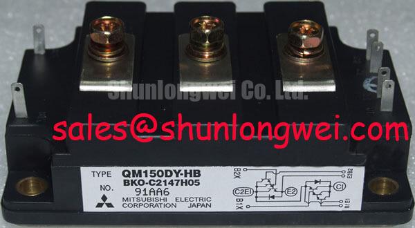
QM150DY-HB | 600V 150A Dual IGBT Module | Technical Review & Specs
An Engineering-Focused Analysis of the QM150DY-HB for High-Efficiency Power Conversion
The Mitsubishi QM150DY-HB is a 600V, 150A dual IGBT module engineered to minimize total power losses in medium-power inverter applications. It delivers a strategic balance between conduction and switching performance, featuring key specifications of 600V | 150A | VCE(sat) 2.7V (max). The primary engineering benefits include a minimized thermal load and a simplified inverter leg design. This module directly addresses the challenge of achieving high efficiency in space-constrained systems by providing a low saturation voltage, a critical factor in reducing heat dissipation. For PWM-controlled motor drives and power supplies up to 40kW, the QM150DY-HB's low VCE(sat) makes it a definitive choice for maximizing system efficiency.
Key Parameter Overview
Decoding the Specs for Reduced System Losses
The technical specifications of the QM150DY-HB are foundational to its performance in demanding applications. The following table highlights the critical parameters that directly influence system design, efficiency, and thermal management. Each value is interpreted from an engineering perspective to aid in component evaluation and system modeling.
| Parameter | Symbol | Test Conditions | Value | Engineering Significance |
|---|---|---|---|---|
| Collector-Emitter Voltage | VCES | - | 600V | Provides a robust safety margin for applications running on 200V-class and up to 400V DC bus lines. |
| Collector Current (DC) | IC | Tc = 25°C | 150A | Enables high power throughput suitable for industrial motor drives and high-capacity power supplies. |
| Collector-Emitter Saturation Voltage | VCE(sat) | IC = 150A, VGE = 15V | 2.7V (Max) | Critical Efficiency Driver: A low VCE(sat) directly minimizes conduction losses, reducing waste heat and allowing for more compact thermal solutions. |
| Power Dissipation | PC | Per Transistor | 540W | Defines the maximum heat the device can handle, a key input for heatsink design and thermal simulation. |
| Isolation Voltage | Viso | AC, 1 minute | 2500V | Ensures high-voltage safety and simplifies UL/IEC compliance by providing reliable isolation between power and control circuits. |
| Thermal Resistance | Rth(j-c) | Junction to Case | 0.23°C/W | Indicates efficient heat transfer from the IGBT junction to the case, crucial for maintaining reliability under heavy loads. |
Download the QM150DY-HB datasheet for detailed specifications and performance curves.
Application Scenarios & Value
Achieving System-Level Benefits in Industrial Power Systems
The QM150DY-HB is best suited for applications where operational efficiency and power density are primary design drivers. Its specifications provide tangible advantages across several industrial domains. What defines the efficiency of the QM150DY-HB? Its low collector-emitter saturation voltage (VCE(sat)) of 2.7V.
High-Fidelity Engineering Scenario: Compact Variable Frequency Drives (VFDs)
An engineer is tasked with designing a Variable Frequency Drive (VFD) for a conveyor system, but the enclosure size imposes strict limits on the heatsink volume. The primary challenge is managing the heat generated by the power stage. The QM150DY-HB's maximum VCE(sat) of 2.7V directly tackles this issue. This low on-state voltage drop is analogous to low friction; it minimizes the energy converted to heat during current conduction. This reduction in thermal load allows the engineer to use a smaller, more cost-effective heatsink while still maintaining a safe operating temperature, thereby achieving the required power density for the compact design.
Other key applications include:
- Uninterruptible Power Supplies (UPS): The module's efficiency contributes to lower operating costs and improved battery runtime during power outages.
- Welding Power Supplies: Its ability to handle high currents and switch effectively is essential for creating stable welding arcs.
- General Purpose Inverters: The integrated half-bridge configuration simplifies the design of one phase leg, reducing assembly time and potential points of failure. What is the module's internal configuration? It features a dual IGBT or half-bridge topology.
While the QM150DY-HB is optimized for systems with up to a 400V DC bus, applications requiring higher voltage blocking, such as those on 690V industrial lines, may find a suitable alternative in the related 1200V QM150DY-24.
Technical Deep Dive
Analyzing the Trade-off: Conduction vs. Switching Losses for Optimal PWM Control
An effective power module design hinges on balancing two primary sources of energy loss: conduction and switching. The QM150DY-HB is engineered to provide a practical solution across the typical frequency range of industrial applications. Conduction loss, dictated by VCE(sat), is the dominant factor at lower Pulse Width Modulation (PWM) frequencies or high duty cycles. You can think of VCE(sat) as the 'toll' paid for current to flow when the device is fully on. The QM150DY-HB's low 2.7V 'toll' ensures minimal energy is wasted as heat during this on-state.
Conversely, switching loss becomes more significant as PWM frequency increases. This loss occurs during the transition between the on and off states. Imagine this as the energy spent opening and closing a very heavy door; the faster you can complete the action, the less energy is wasted. The switching characteristics detailed in the datasheet (t_on, t_off) quantify this speed. The QM150DY-HB provides controlled, well-defined switching times that prevent the device from lingering in a high-resistance transitional state, thereby conserving energy during each cycle. This balance makes it highly effective for applications operating in the 5 kHz to 15 kHz range, common for motor control and power supply designs.
Frequently Asked Questions (FAQ)
How does the 2.7V max VCE(sat) of the QM150DY-HB translate to real-world system efficiency?
A lower VCE(sat) directly reduces power loss (P_loss = VCE(sat) * IC). In a 150A application, every 0.1V reduction in VCE(sat) saves 15W of heat per transistor. This translates to higher overall system efficiency, lower heatsink requirements, and improved long-term reliability due to reduced thermal stress on all components.
What is the primary benefit of the dual (half-bridge) configuration in the QM150DY-HB package?
The dual configuration integrates two IGBTs and two freewheeling diodes needed to form a complete inverter phase leg into a single, thermally efficient package. This simplifies the PCB layout, reduces stray inductance between the switches, and minimizes assembly complexity compared to using four discrete components. This integration is a key feature of a modern IGBT Module.
For what range of PWM frequencies is the QM150DY-HB best suited?
Based on its balance of low conduction losses and moderate switching speeds, the QM150DY-HB is optimally suited for applications with PWM frequencies ranging from approximately 2 kHz to 15 kHz. This range covers the vast majority of industrial motor drives, UPS systems, and welding applications where efficiency is paramount.
Strategic Design Implications
Integrating the QM150DY-HB into a power system is a strategic decision that prioritizes efficiency and reliability. Its datasheet parameters confirm its suitability for mainstream industrial applications, offering designers a dependable building block for creating power converters that not only meet performance targets but also contribute to lower operational costs and enhanced system longevity. This focus on fundamental performance characteristics ensures its relevance in designs where proven technology and predictable behavior are valued over cutting-edge but complex alternatives.